You are currently browsing the archives for the security hardware category


Securitech Lexi Electrified Exit Device Trim

Great Problem Solver
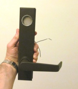
The Securitech Lexi series retrofit exit device trim is available with a variety of back plates and adapters that allow it to be used with most major brands, including many surface vertical rod and concealed vertical rod exit devices.  Compatibility with a variety of vertical rod devices is a major plus.

I mean, anybody can electrify a rim exit device by simply installing an electric strike.  However, while it is possible to install an electric strike on a vertical rod device it rarely brings a good result.  First of all, in order to use an electric strike you have to first lose the bottom rod.  That just leaves one latch at the top of the door to provide all the security.  If it is a tall door or a flexible door – like an aluminum storefront door – you can pull the bottom open several inches with just that top latch holding it.  Add a little time and a little hinge sag and pretty soon you have no security at all.

The other solution is electric latch retraction, or electric latch pullback, as some manufacturers call it:  relatively expensive compared with a Lexi trim.  Also, electric latch retraction is a fail secure only solution when locking trim is used and therefore may be inapplicable to fail safe installs such as stairwells, unless passage function (always unlocked) trims are used.

I notice that right out of the box the Lexi is very self contained.  Other than a tiny box containing mounting screws, tailpiece operators, and a cylinder collar and cam, what you see is pretty much what you get.  It’s pretty hefty for its size – it is designed on the slim side so as to be usable on narrow stile as well as hollow metal or wood doors.   This does mean that the installer may have to be a little creative when replacing a larger exit device trim with the Lexi.
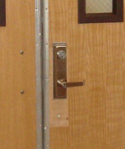
Installation instructions are easy to follow and short – only four pages, including the template. Something I would have liked to see in the instructions, but didn’t, was current draw.  If I am installing one of these, the number of amps it draws are not going to matter much to me.  But if I am installing twenty of them and want a centralized power source, now it’s an issue.  Yet it isn’t anything that an experienced low voltage specialist with a ammeter can’t find out in two seconds.

One of the great innovations I noticed right away is the rotation restriction clip that allows the installer to customize tailpiece rotation to the exit device.  I do not think that this is handled better by any other manufacturer.  Correct degree of rotation often determines whether a trim will work or not, and to have a trim that has degree of rotation so easily selectable is damn nice.
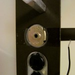
As mentioned in the sales literature, since Securitech’s Lexi trim is compatible with so many exit devices, if you have a facility with different brands of exit devices dispersed throughout, you can install access control and unify the exterior appearance at the same time.  And in addition to being versatile it is also durable.  Forcing the lever only causes its internal clutch to break away, and it can easily be set right by rotating it back the other way.

All in all the Securitech Lexi trim seems to be a well built, versatile problem solver.  I think you’ll find it useful in many access control installations.
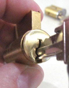
The Keyway: Gateway to the Cylinder

The keyway is the shape of the keyhole of the lock cylinder into which the user inserts the key.  The keyway is designed to allow only keys of the correct shape to be inserted such that, when properly made, they will align the pin tumblers properly and operate the cylinder.  If you view a key from the tip, you can see how the shape of the key corresponds to the shape of the keyway.


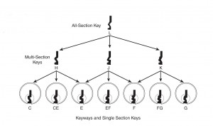
The theory behind the keyway is to let only certain kinds of keys in and keep all others out, and keyways do this with varying amounts of success.  A variation on this idea is the “sectional” keyway system in which keys of slightly different keyways are allowed to “pass” into the cylinder keyway.  See the diagram of the Schlage hierarchy of keyways below:

The keyways shown at the bottom of the chart are designed to fit in only one keyway.  Unlike the keyways shown in the top two rows, actual locks have the keyways in the bottom row.  The keyways shown in the second row could be called sub-master sectional keyways because keys cut on blanks of these keyways will each pass several of the keyways in the bottom row.  Keys cut on the “L” keyway shown at the top of the chart will pass all of the keyways below it.  This keyway is designed to be used only at the level of Master or Grand Master key.

Unfortunately, some key duplicators use the “L” keyway key blanks to cut keys of any sectional keyway they may currently not have in stock.  This shoddy practice degrades the security of a master key section that depends on sectional keyways for security.

Restricted Key or Restricted Keyway?

Keys can be stamped with the words, “Do Not Duplicate” or “Property of [insert name of institution or government agency here],” and that may stop some honest people from getting the key copied.  The term, “restricted key,” however, usually means factory restricted keyway, and a factory restricted keyway can effectively inhibit unauthorized key duplication.

How Does a Factory Control a Keyway?

The most effective way to control unauthorized key duplication is to make the key blanks as difficult to get as possible.  Key blanks are like blank paper to a copier.  Imagine copy paper protected by a patent owned by a paper mill.  The only place to get the paper would be the paper mill.  Thus, one of the ways security hardware manufacturers protect a keyway is to protect it by patent law.  Part of that protection is aggressively pursuing anyone who violates the patent with lawsuits and other legal instruments to prevent patent infringement.

Another way factories protect keyways is to keep records of who is using what keyway and where.  Many companies have restricted key programs – Schlage Primus, Kaba Peaks and Medeco are a few examples.  Factories may keep signatures of end users on file.  In this case, requests for restricted products must be accompanied by a document that is signed with the correct signature or the factory will not release the product.

Some restricted keys come with an ID card that authorizes the card holder to get keys made.  This is less secure than key duplication that is controlled at the factory, but it is a step up from keys that anyone can get made at Home Depot.

Keyways and Key Bumping

In order to use a bump key to open a lock, the key bumper needs to have the right blank.  You cannot bump a cylinder with a bump key that has the wrong keyway.  It won’t go in.  Therefore, having a lock that has a somewhat rare keyway is a very easy and inexpensive way to make unauthorized entry by key bumping difficult.  Most of the people out there bumping locks open are not the brightest bulbs in the lighting fixture.  Challenge them with a hard-to-identify keyway and they will most likely be defeated.


Multi-function Doorways, Part Two

Secured stairwell doors are among the most basic multi-function door applications.  In most jurisdictions they must (usually)* be both unlocked and positively latched in the event of a fire.  Unlocked so that if a person, fleeing into the stairwell during a fire, finds the stairwell full of smoke, they can safely exit the stairwell.  Positively latched so that the door will remain latched closed against the spread of the fire.

Until there is a need for access control, a passage function mortise lock, cylindrical lock with UL listed latch or exit device with passage function trim are fine.  The application begins to get interesting when the need arises to lock a stairwell door.

Right up front, electric strikes are out of the question because of the unlocked/positive latching requirement mentioned above.   It is not possible to positively latch a door when the electric strike is unlocked.  There is no such thing as a fire rated, fail safe electric strike.  If you configure a fire rated electric strike to be fail safe it voids the fire rating.

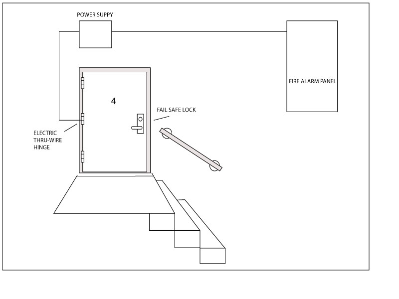
Since electric strikes are unusable for this application, that leaves either electric locks or electromagnetic locks.  Both have advantages and disadvantages.  Fail safe electric locks positively latch whereas mag locks allow the installer to us the existing hardware on the door to accomplish positive latching.  Electric locks require running wire through the door and some means of getting the wire from the frame into the door, such as an electric through-wire hinge.  Not all inspectors like electromagnetic locks, so before you install them be sure to check with your local Authority Having Jurisdiction (AHJ ) – that is, Fire Marshal or Building Inspector.

If the stairwell door already has a fire rated exit device installed, there is probably a fail safe electrified trim available for it.  Once again, this means an electric through-wire hinge or other power transfer device would be required.  Sometimes existing exit devices are incompatible with the electrified trims available for that brand and model of device.  If that is the case, the exit device might have to be replaced with one that is compatible with electrified trim.

Alternatively, there are after market request to exit (a.k.a. RX) switches available for most exit devices.  One could be used to release an electromagnetic lock on the stairwell door.

Usually it is required that all electric locking devices on stairwell doors be controlled by the fire alarm panel.  When the fire alarm is in a state of alarm, it unlocks all the stairwell doors.  Two conductor wire is run from the fire alarm panel contacts to a special fire alarm relay in the power supply that powers the electric locks on the stairwell doors.  The alarm panel opens the circuit, causing the state of the fire alarm relay to change, thus powering down the fail safe locks and thereby leaving them unlocked.

An important detail:  technically speaking, according to most building and life safety codes, fire rated doors can only be modified in a fire rated shop.  Therefore if you field cut a raceway for an electric wire through the cross members of the door, for example, you are probably voiding the fire rating.  I have never heard of anyone being called on this, but it is good to keep in mind.  Just like it is good to keep in mind that the AHJ has total authority over what you can or can’t install.  Best make sure you’re on the same page with her or him, otherwise they do have the power to make you remove what you installed and replace both door and frame to repair the damage.

Happy hardware and good luck to you.


*Some jurisdictions specify that not all stairwell doors need be unlocked in the event of a fire, only certain doors.  For example, I have known some places where code was the door had to be unlocked at every fourth floor.  Check with your local AHD to find out what the rules are for your location.


Hot Stuff: Continuous Duty Electric Locking Devices

The Ohm Symbol

I regularly hear complaints about electric strikes, cylindrical locks or mortise locks that are hot to the touch.   When I ask, I am always answered that, yes, the device is being used in a continuous duty application.

Continuous duty means that the electric lock or strike is powered continuously, usually for several hours a day.  Most fail safe locks and strikes are run continuously, since they are usually locked part of the day and they require electric power to lock.  Whenever a door is kept unlocked by using an electrical timer, the lock or strike that is controlled by the time is run continuously for part of the timing cycle.

Heat in an electric lock or strike is caused by resistance in the electrical circuit as it passes through the coil of the solenoid inside the device.  Often this heat is sufficient to “burn out” the solenoid.   The solenoid does not actually catch fire, usually.  The term, “burned out” refers to a solenoid that has been ruined by excessive heat so that it no longer functions.

Heat from electrical resistance is exacerbated when there are problems with the supply of power.  For example, if the power supply provides less than sufficient amperage to constantly power the solenoid, the solenoid will ‘run’ hotter.  Similarly if there is a current drop because of a long wire run with inadequate wire gauge, the solenoid will not get sufficient current and will run hot.  Also if the voltage supplied is significantly higher than the solenoid is rated to accept, that could create a heat problem as well.

Often, however, there is no detectable reason for the solenoid to run hot.  Sometimes, it seems, they just do.

A great way to mitigate the problem of the hot lock or strike (when all power supply problems have been solved) is to use an electrical device in line with the electric lock or strike that provides it with a full inrush voltage and current upon activation and then reduces the voltage and/or current to a holding level, allowing the solenoid to run cooler.

Several companies offer these units.  Here are some examples:

  • HES:  Model 2005M3 Smart Pack controller
  • COMMAND ACCESS:  CRU-2 current reduction unit
  • TRINE:  LC-100 line conditioner


Full Height Housings for Electromagnetic Locks

Maglocks are generally great problems solvers, but they also create problems.  One significant problem is the fact that they are usually installed on the header, and therefore only lock the top of the door.  If the only lock on the door is a magnetic lock and the door is fairly flexible, a reasonably strong person may be able to pull the bottom of the door open four or more inches.

One solution to this problem is to install mags top and bottom on the lock side leg of the frame rather than on the header.  If you have an opening that measures at least 35 inches from stop to stop and you use magnets that are three inches wide or less, you can install mags in the opening and still have 32 inches clear to comply with the American Disabilities Act.  The problem with this idea is that no matter where they are installed in the opening, users are likely to bump into them with some body part or other.

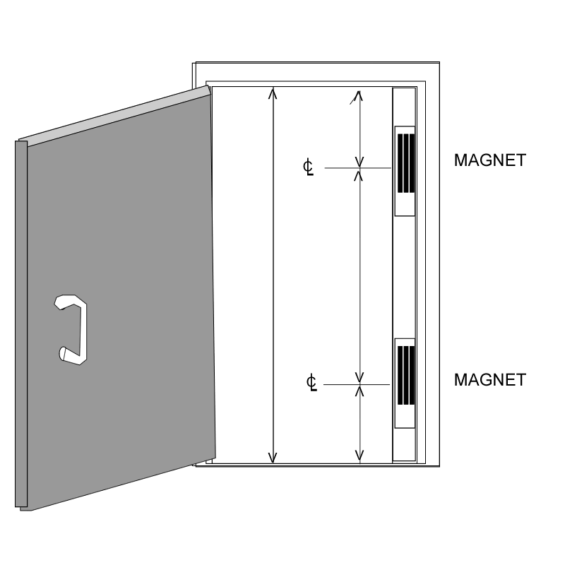
Enter the full height housing for electromagnetic locks, an enclosure that houses one or two maglocks and mounts on the stop of the lock side leg of the door jamb as illustrated below.

The illustration above is one I prepared for a customer so that I could order a custom built, full height housing for two electromagnetic locks.  The drawing shows the dimensions I requested as indicated by the lines with arrows at both ends:  height of the opening from threshold to header stop; distance from header stop to center line of upper maglock prep; distance from threshold to center line of lower mag prep; and distance between the center lines of the mag preps.

Provided the opening is at least 35 inches clear and the housing is no more than three inches wide, the opening will still comply with ADA after the full height housing system is installed.


Multi-function Doorways, Part One

As seen in Doors and Hardware Magazine.

Whenever something is invented, humans find more uses for it.  This is certainly true for door automation and electric locking.  It was not long after people realized a door could be unlocked remotely using an electric strike and a door could be opened automatically using a power operator (automatic door opener) that they began using these devices together.   Of course this combination of devices was soon interfaced with intercoms.  Exit devices with electric latch retraction and electromagnetic locks were thrown into the mix, as well as access control, delayed egress and/or security interlock systems.  Any of these systems alone is sufficient to complicate an installation, but when you start to use several on one opening, that’s when things really start to get interesting.

A hospital can be one of the best places to run into a doorway that needs to perform many functions (pun intended).  Hospitals seem to have more varied reasons to keep different people out at different times, or to let them in or out by different means.  In addition to standard life safety and security issues, hospitals also have to anticipate the needs of patients who may be under the influence of medication and/or mental disorders and/or have physical limitations.  Some patients must be kept inside for their own safety while all patients must be able to exit swiftly and safely in the event of a fire.

Let’s use as an example a hospital emergency ward entrance used primarily by ambulance drivers.  The hospital wants only ambulance personnel and the security guard  to be able to activate the power operator, and to control access by use of a remote switch operated by the security guard  for the general public and an access code by hospital employees (other than ambulance personnel).

Since it is a pair of doors, concealed vertical rod exit devices are the most efficient, safe and secure way to lock them and provide reliable free egress in the event of an emergency.  However, since there is a power operator involved, these devices must be equipped with electric latch retraction; and since use of the power operator was to be limited, a second electric means of opening the door would be required.

A simple way to solve the problem of the second means of unlocking is by using electrified exit device lever trim with one of the concealed vertical rod exit devices.  Persons not requiring the power operator can get in by using the access control, or the security guard  can “buzz” them in using one of two remote buttons.  Because there will be two means of unlocking the door electrically, the security guard  will need a small desk unit with two buttons:  one that activates the power operator and electric latch retraction and one that activates the electric exit device trim.

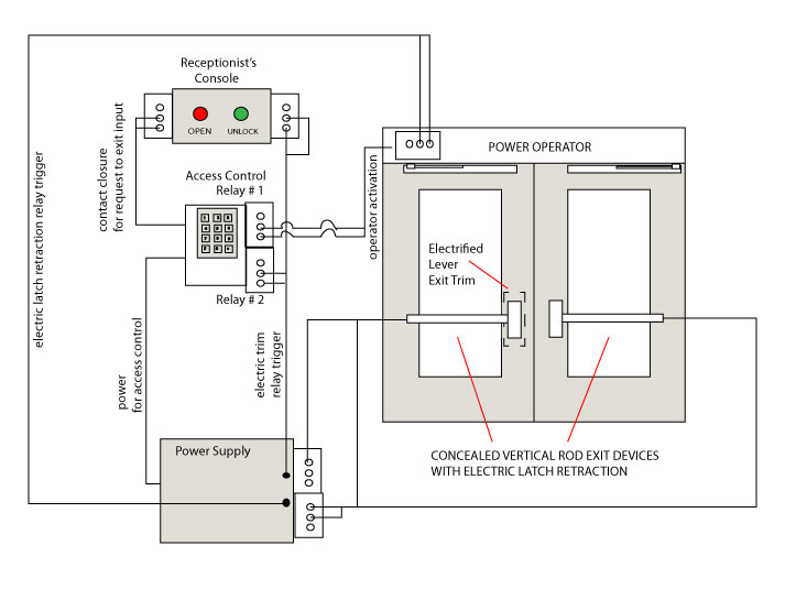
Below is an amateur wiring diagram (made by me) of how, basically, the system works.

Central to the concept is an access control device with two relays and a request to exit input.  This allows several of the connections to be made through the access control system.  If the access control system on site does not provide more than one relay, the same functions can be accomplished by using additional relays in the power supply.

The system as shown in my illustration above works like this:

Ambulance personnel activate the power operator using the access control system.  The access control system signals the power operator via contact closure in Relay #1.  The power operator triggers the relay in the power supply to retract the latches of the exit devices, then opens the door.

Other authorized hospital personnel use the access control system to unlock the lever trim.  The access control system changes the state of Relay #2, triggering the relay in the power supply to unlock the trim.  They turn the lever, pull the door open and walk in.

Injured people arrive on foot at the Emergency Room entrance.  The Security Guard sees them (or is notified by intercom, not shown) and lets them in by pressing the red button, activating the power operator, or by pressing the green button that unlocks the exit device trim.

There exist many possible variations of this system.  Knowledge of access control systems and door hardware are required, but the most important principal in play is the use of contact closure to signal multiple devices.


Exit Device Checklist

See also Exit Device Basics

Here are a few questions you need to be able to answer before you order exit devices:

  • Is the door made of wood, hollow steel, Fiberglas, aluminum and glass, or all glass?
  • Is the door is fire rated or non-fire rated?
  • Door width if single door or pair of doors with center mullion?
  • Door width and height if for a pair of doors without mullion?
  • Door thickness?
  • Exit device finish?
  • Will this be an exit-only device, or will there be outside trim?
  • If there is outside trim, what function is it?

It will save you time and aggravation if you know the answers to these questions before you call your hardware vendor.

You may also want one or more of these or other mechanical options:

  • Cylinder dogging (not available on fire rated devices)
  • Less bottom rod (for vertical rod exit devices)
  • Double cylinder (trim locked or unlocked from inside secured space)

There may also be electrified options:

  • Does the exit device need to have electrified trim?  If so, fail safe or fail secure?
  • Does the exit device need to have electric latch retraction?
  • Does the exit device need to have push pad or latch monitor switches?
  • Do you need a delayed egress exit device?

Save time and money by gathering the necessary facts before shopping for exit devices.

The Elusive “Touch Chip” Credential

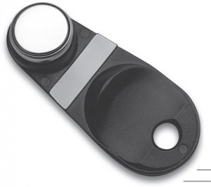
A few years ago, Ingersoll Rand (IR) purchased Locknetics Security Engineering in Connecticut, and since then gradually rebranded the line as Schlage Electronics.   A little over a year ago, as part of the process of closing the Connecticut facility, Schlage Electronics started phasing out its TR80 and TR81 touch readers.  These readers were based on the old technology of the Dallas chip, otherwise known IR/Locknetics land as the touch chip or iButton.  By the end of 2010, Schlage phased out all commercial electronic locking products that incorporated touch chip readers, such as touch readers and locking technologies that incorporated the touch reader, such as the CM line of computer managed locks and their electromagnetic locks with on-board access control.

When the new price books were released in January 2011, the touch chip credential was completely absent.   When questioned about legacy systems, representatives from IR indicated that touch chip users should migrate over to prox tags.  With the new AD and CO series electronic locks, Schlage made available new software and a new hand held programmer (the HHD-KIT) that is backwards compatible with the old hardware.  They also produced a tag with a prox chip on one side and a touch chip on the other so that legacy facilities would be able to carry both credentials over the period of years during which the old CM or other series locks would age out of the system.

One might think that the touch chip has completely faded from the Schlage Electronics scene, but such is not the case.  Looking through the Multi-Family Price Book what do I discover but the new SRT-100 touch reader and a barrage of “iButton” touch chip credentials such as the one pictured.   The new CT-5000 controller that replaces the old CT-1000 controller is also available for those who need to replace ailing legacy systems.  It is my understanding that the iButtons that appear under the multi-family division are fully compatible with legacy technologies such as CM locks or KC-2 series locks.

There is also a new line of smart residential locks that incorporate touch chip technology.  So it is safe to say that touch chip technology is not going to disappear anytime soon.  So if you have a large facility full of old Locknetics products that take iButtons, don’t panic.  At least for now you can still get them.


Interconnected Locks


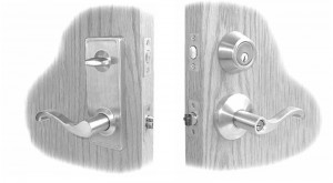
Sargent 7500 Series Interconnected Lock

An interconnected lock is actually two locks that are connected by an assembly that retracts both the deadbolt and the latch simultaneously when the inside handle is turned.   This is done to fulfill the life safety requirement under NFPA 101 that egress should be accomplished by one motion with no prior knowledge necessary, and at the same time provide the user with the security of a deadbolt.  The same function could be provided by an entry function mortise lock, but interconnected locks are cheaper, since they are usually cobbled together out of (usually) a grade 2 cylindrical lock and a tubular deadbolt.

The history of the interconnected lock is a twisted, strange story of different companies reinventing the wheel with different distances between the centerlines, connected or separate latch/bolt assemblies with correspondingly different strike preps, and radically different hole patterns on both interior and exterior door surfaces.  The end result has been many, many doors and frames prepped for locks that are now irreplaceable.

Today, preps are much more standardized.

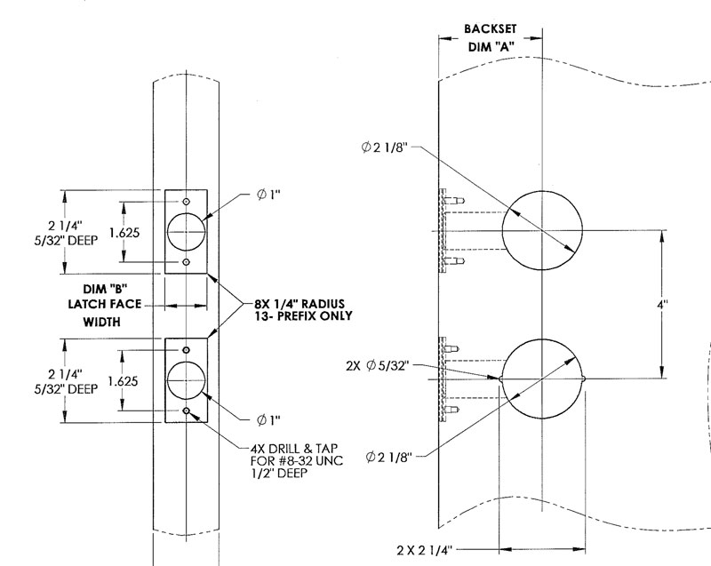
These are some of the interconnected locks available today and the measurements of their preps:

  • Falcon H Series – 4 inches CTC, 1-3/4 inch hold above, 2-1/8 inch hole below
  • Schlage H Series – 4 inches CTC, 1-1/2 inch hole above, 2-1/8 inch hole below
  • Schlage S200 Series – 4 inches CTC, 1-1/2 inch hole above, 2-1/8 inch hole below
  • Schlage CS200 Series – 4 inches CTC, 2-1/8 inch holes above and below
  • Sargent 75 Series – 4 inches CTC, 2-1/8 inch holes above and below
  • Yale 4800LN series – 4 inches CTC, 2-1/8 inch holes above and below

Replacing any of the locks above with any of the others would not present an enormous problem.


Sargent 7500 Series Door Prep

New PS914RFK Retro-fit Kit from Von Duprin

According to IR tech support, the PS914RFK is a bracket and main board assembly designed to install into existing PS873 enclosures.  The idea is to ease PS873 replacement and it looks to me like it will accomplish that.

In addition to the PS873, you will need to replace all existing option boards that are present.

  • To replace 871-2, use 900-2RS
  • To replace 873-BB, use 900-BBK if you need batteries included.  If not, use 900-BB for the board only
  • To replace 873-FA, use 900-FA
  • To replace 873-4TD, 873-AO, or 873-SI, use 900-4RL
  • To replace 873-2Q, use 900-2Q

The following boards have been discontinued:

  • 873-AL
  • 873-AC
  • 873-DE

In several pieces of Ingersoll Rand literature I have seen the 900-BB board depicted as if it includes batteries.  It does not.  So if you want your battery kit to come with batteries, you need to get the 900-BBK.


Tags