You are currently browsing the Door Hardware Genius posts tagged: power supply


Choosing a Power Supply for Electric Locking Devices

Allegion PS904 Power Supply with optional boards.

There are many ways to lock a door electrically. Here are a few of the most popular:
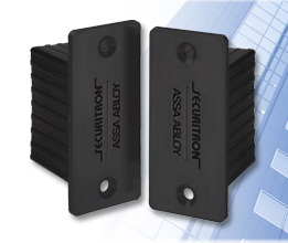
  • Electric Strike
  • Electromagnetic Lock
  • Electrified lock
  • Electric Latch Retraction exit device

Voltage and Current

Two main factors are universal in choosing a power supply, but some kinds of electric locking devices require special considerations. The first universal consideration is the voltage required by your electric devices. The second is the amount of current drawn by these devices.

As of this writing, most strikes, magnets and locks are field selectable for a variety of voltages, mostly 12 or 24 VDC. Some are not field selectable. Almost all electric latch retraction exit devices are 24 VDC. The important factor is, what voltage will be used to power the devices. Voltage is important (aside from the fact that running an electric device on the wrong voltage may cause a fire) because voltage affects current draw. Current draw (measured in Amperes, or ‘Amps’) determines the need for power supply capacity.

Following are examples of how the voltage affects current draw:

HES 1500 series electric strike:

  • .24 Amps @ 12 VDC
  • .12 Amps @ 24 VDC

Schlage Electronics M490 electromagnetic lock:

  • .65A @ 12 VDC
  • .35A @ 24 VDC

SDC 7800 series electrified mortise lock:

  • 600 mA @ 12VDC
  • 300 mA @ 24VDC

Yes, there is a trend here. 12VDC draws twice as much current as 24VDC. Good to know. A little clarification may be in order:

.24 Amps = 240 mA

Now that we have that cleared up, let’s say that we have a six-door access control project and we’re using 24VDC. On four of the doors we’ll use the HES 1500; on one door we’ll use the M490 mag and on the last door we’ll use the SDC 7800 electrified mortise lock.

Just for variety, let’s add a Sargent 80 series exit device with motorized latch retraction:

  • 1 amp @ 24VDC

The arithmetic looks like this:

.12 + .12 + .12 + .12 + .35 + .30 + 1 = 2.13 Amps total current draw

You want to allow at least a 25% cushion so that the power supply does not have to work too hard. Therefore, rounding up, a 3-Amp power supply would be a safe bet.

Distance of Wire Run

The distance between the power supply and the appliance to be powered is also an important factor. It may determine how many power supplies you need.

Using an online voltage drop calculator I was able to determine that a 1,000-foot wire run (one-way) using 18-gauge two-conductor wire, with a current draw of 120 mA, the voltage drop will be less than 1 percent. With a 1-Amp current draw, and all other parameters the same, the voltage drop would be about 27 percent. Therefore, whereas the 1,000-foot wire run would not be a factor to run one HES 1500 strike a 120 mA, it would be a factor in powering the Sargent exit device with electric latch retraction at 1 Amp at that distance. This might mean that a separate power supply would be installed much closer to the Sargent and another power supply could power all the other devices.

Voltage drop can be managed to a degree by increasing the gauge of the wire. Using the Sargent electric latch retraction example, this time using 12-gauge wire instead of 18-gauge wire, voltage drop on a 1,000-foot one-way wire run would be 14 percent instead of 27 percent. Using thicker wire combined with moving the power supply closer to the device can mean the difference between a system that works well for years and one that soon fails.

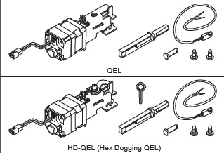
Electric Latch Retraction Exit Devices

In many cases the industry has shifted away from solenoid-driven electric latch retraction exit devices and moving more and more toward motor-driven latch retraction. Nevertheless, those solenoid-driven devices are still out there and many are still being sold. From a power supply point of view, it is very important to understand the difference.

When solenoids are activated, the draw an “inrush” of high current for a fraction of a second. For example, a Von Duprin EL99 rim exit device draws 15 Amps at 24 VDC for one third of a second, requiring it to have a special power supply. Their power supply for this application is the PS914-2RS, which will power up to two EL devices. What makes the power supply special is (1) the circuit board equipped with capacitors that gather the current and release it when it’s big enough to do the job and (2) a delay timer that allows the power supply to power up two devices one at a time, one-third of a second apart.

There are other power supplies that will work in this application: the Altronix STRIKEIT series power supplies, or the Command Access PS220 with PM300 power booster are two such. Each will power up to two solenoid driven electric latch retraction exit devices.

As shown earlier in this article, motorized latch retraction exit devices also draw more current than other kinds of electric locking devices. However, they draw much less current than solenoid driven latch retraction exit devices. Most manufacturers say to allow 1 amp per device. Check the install instructions for your particular device to be sure.
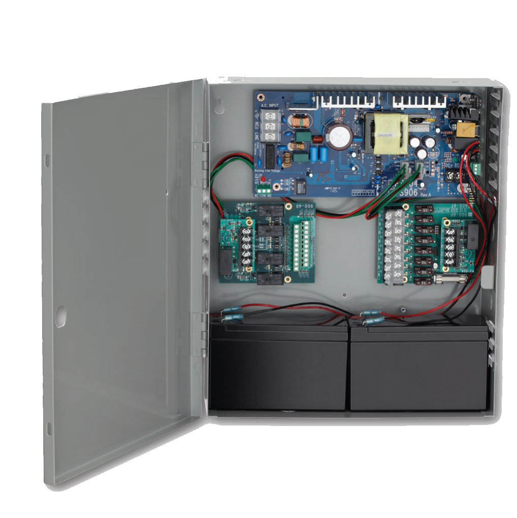
Options

Following are some accessories you can add to make your power supply easier to install and/or service, or to add functionality.

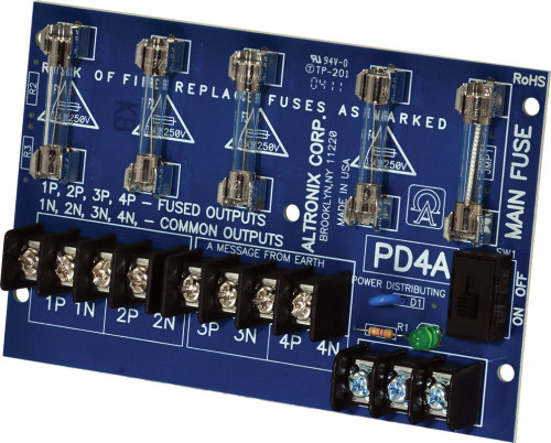
Power Distribution Board

If you have a power supply with one or two sets of outputs and need more outputs, you can add a power distribution board. The power distribution board distributes power evenly among several sets of output contacts. This can come in handy when troubleshooting a power supply that is powering multiple devices.

Altronix PD4 power distribution board.

Relay Board

Relays are electrically operated switches. You flick the lights on in your room with your finger. Instead of a finger, the relay uses electricity. Relays typically draw a very small amount of electrical current. This can be useful in a variety of applications.

Security Door Controls relay board.

One example is in a simple access control system, where a receptionist pushes a button to activate an exit device with electric latch retraction that draws 1 Amp, 150 feet away. Instead of of running 1-Amp current from the power supply to the pushbutton, from the pushbutton to the device, and from the device back to the power supply, use the pushbutton to trigger a relay in the power supply to power the device. Only the few milliamps needed to power the relay will run back to the pushbutton. This makes the system much safer for the receptionist and avoids any voltage drop problems from the extra wire run back to the pushbutton.
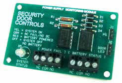
Fire Alarm Relay

The fire alarm relay option allows connection to the fire alarm panel, so that in the event of an alarm the panel can shut off the power supply.

Logic Board

Logic boards are boards with multiple relays and internal switches. These are used to perform more complex functions, such as activating electric latch retraction exit devices and then, a fraction of a second later, activating an automatic door opener.
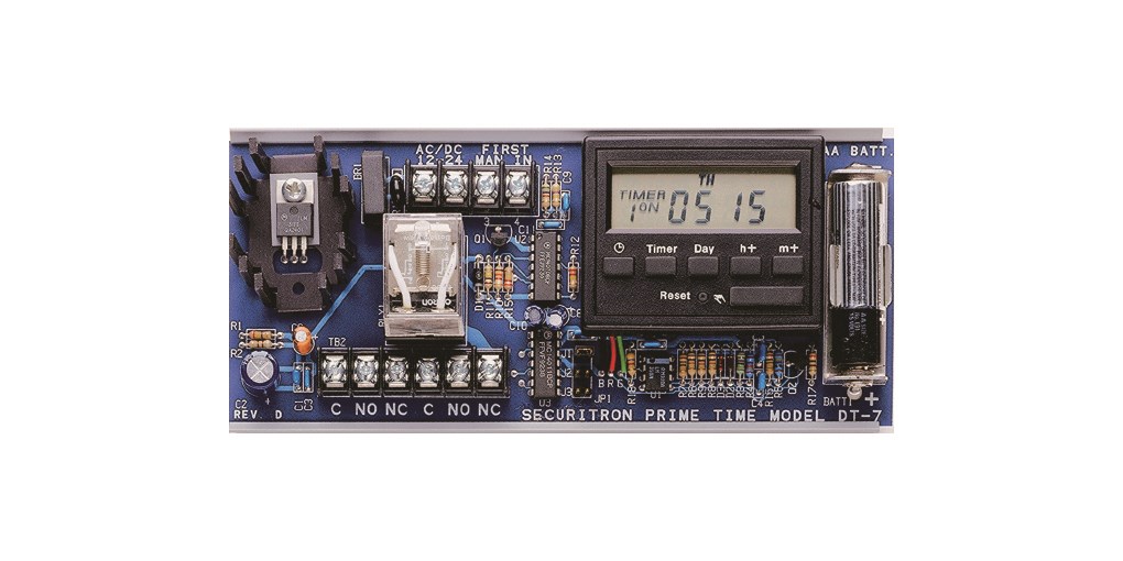
Timers

There are two main types of timers found in power supplies that are used with electric locking devices: 24-hour timers and delay timers.

24-hour timers are used to keep doors locked or unlocked for variable periods at specific times. Typically these timers can be programmed for a number of lock or unlock events. Simpler units might be used to unlock a door in the morning and then lock it back up at night every day. More versatile units can be programmed to behave differently on weekends and holidays.

Delay timers are used to time the re-locking of the electric device after it has been activated. For example, the receptionist pushes the button at her desk and immediately lets go. The timer powers the electric strike for six or seconds to allow the visitor time to push the door open.

Securitron DT-7 timer

Von Duprin QEL Kit Diversity

qelhdqel

QEL and HD-QEL modular conversion kits.

Von Duprin offers several versions of its QEL (Quiet Electric Latch retraction) conversion kits for its 33, 35, 98 and 99 series exit devices.  The variations are:

  • Modular (no baseplate)
  • Modular, with connectors (Molex)
  • Modular with hex dogging
  • Modular with hex dogging and connectors
  • With baseplate, specify 3-ft. or 4-ft.
  • With 3- or 4-ft. baseplate and connectors
  • With 3- or 4-ft. baseplate and hex dogging
  • With 3- or 4-ft. baseplate, hex dogging and connectors

None of the modular kits come with baseplates.  Kits with baseplates offer a small ease-of-installation advantage because replacing the whole baseplate is slightly faster than field installing the modular kit onto an existing baseplate.  Modular kits can be installed in either 3- or 4-ft. devices, so if you want to have one kit on your truck, a modular kit would be the logical choice.

Which modular kit should you get?  I would suggest the HD-QEL Modular Conversion Kit with Connectors.  If you don’t want hex dogging, you can use a blank cover plate or plug the dogging hole in the existing cover plate.  If you don’t want the connectors, you can cut them off.  And since at the time of this writing there is no price difference between a modular kit with connectors and/or hex dogging, or without connectors and/or hex dogging, you might as well get the one with all the bells and whistles.  As I indicated, you can always dial it back.

While Von Duprin recommends any of their PS900 series power supplies together with their 900-2RS relay board to run their QEL devices, many installers are using their own power supplies and this seems to be working just fine.   QEL draws a 1-amp inrush.  I recommend allowing 2 amps for each QEL on a power supply, and it is always good to isolate them on their own set of contacts in the power supply if possible, using a power distribution or relay board.   If these contacts can be protected by a fuses or circuit breakers, so much the better.   A regulated and filtered power supply is also a plus.


Unlike many power supplies, I am both unregulated and unfiltered … and I like it that way.


locksnsafescom

Your source for quality security products with superior service!

Experiencing the New Von Duprin Chexit

Chexit door label from Chexit installation instructions.

Von Duprin Chexit door label from Chexit installation instructions.

Last year Von Duprin began shipping Chexit self-contained delayed egress exit devices that are motorized instead of solenoid driven.  Since they are motorized, the new Chexits draw less current and will probably be more reliable than the previous solenoid-driven version. This means a less serious, less expensive power supply, less need for high capacity, high gauge, high cost wire and greatly increased workable wire run distances – all good things.

The new Chexit will do everything the old Chexit did, including release of the outside lever trim when the external inhibit function is activated by access control or another external switch.  That remains a way to get access control out of a Chexit by simply adding a blank escutcheon or other unlocked outside trim to the Chexit exit device.

As of this writing Exit-only function Chexit devices were being shipped less the part number 040193-00 cable used to connect the E996L to the Chexit PC board.  The cables are only provided if you order the Chexit from the factory with trim, but that is okay as long as you want to use no trim or non-electric trim.  Electrified trim is a means to provide fail secure access control from the trim side, so if the fire alarm goes off and powers down the Chexit, the fail secure electrified trim will stay locked.  Entry can still be gained by key.

On another note, recently I was involved in an application where the installer was replacing a mortise exit device and wanted delayed egress from the push side and free ingress from the pull side.  Luckily it was a mortise device, so all I had to do was provide a Chexit mortise exit device with blank escutcheon (passage function) trim because THE MORTISE LOCK ACTS INDEPENDENTLY FROM THE CHEXIT ON THE TRIM SIDE. Cool. 🙂

Bear in mind that  the Chexit remains active while people are using the passage function trim to get in, so if they happen to depress the touch bar, say by bumping it up against the wall for two seconds, they may activate the Chexit alarm.   Von Duprin Tech Support suggested a palm switch on the trim side to activate the inhibit circuit in the Chexit while a person enters from that side.


It was fun, easy, and I looked like a … Hardware Genius.

Securitron’s new PowerJump ICPT™ Inductive Coupling Power Transfer

Securitron’s new PowerJump ICPT™

Securitron’s new PowerJump ICPT™

The door hardware industry breathlessly awaits the debut of Securitron’s new PowerJump ICPT™ Inductive Coupling Power Transfer.  The PowerJump is Securitron’s miraculous new device that may put a significant dent in the electric through-wire hinge market.  I mean, why would you drill a half inch hole the width of a 36-inch door when you could install this little pair of black boxes on the lock side?

I downloaded the installation instructions from the Securitron web site to check out product attributes and characteristics.  The first thing I noticed, having spent much of my career working with wooden doors, that the Securitron PowerJump ICPT is a bit friendlier to a hollow metal door or frame install than it is to a wood door or frame install.  Because the body of the unit is almost the same size as the face, the installer must take great care to cut a very clean hole for the body so that the hole does not exceed the size of the face.  This can be a little tricky when using a speed bore bit (or auger bit as mentioned in the instructions) to drill the two deep holes for the mortise pocket before cutting in the face.

One trick I have used to use when installing mortise locks was to cut in the face first and get that nice and clean before drilling the holes.  I had good success with this because it gave me a very clear outline to stay within – much like coloring inside the lines with crayons in kindergarten.  Installing the PowerJump is a lot like installing a really small mortise lock, actually.  The face is the same width and a standard architectural grade mortise lock – 1-1/4 inches.

The PowerJump ICPT draws 500mA at 24 volts DC on the frame side, will transmit it across up to 3/16 inch of empty air and output either 250mA at 24VDC or 500mA at 12VDC on the door side.  500mA seems a little slim to be powering an electrified mortise lock.  Usually I like to see a bit of a cushion when it comes to current, so I would usually not power a device that requires 250mA at 24 volts DC, like a Sargent electrified mortise lock, with a power source that provided no more than the 250mA required.  I’d be a lot happier with a power source that has a capacity at least 1.5 times as great as the appliance being powered.

However, the average electrified hinge with 28-gauge through-wires only has a current rating of about 160mA and we have been powering electric mortise locks with these for decades.  Since I am not an electrical engineer I am not sure how that works, but it does.  I am also mystified by the science behind transmission of electrical current by induction.  Therefore, like most installers, I trust Securitron to produce yet another innovative product that works well.   I’ll be waiting to hear how installers like it when it is finally released.  I know I’ll hear about it one way or another.

Securitech Lexi Electrified Exit Device Trim

Great Problem Solver

The Securitech Lexi series retrofit exit device trim is available with a variety of back plates and adapters that allow it to be used with most major brands, including many surface vertical rod and concealed vertical rod exit devices.  Compatibility with a variety of vertical rod devices is a major plus.

I mean, anybody can electrify a rim exit device by simply installing an electric strike.  However, while it is possible to install an electric strike on a vertical rod device it rarely brings a good result.  First of all, in order to use an electric strike you have to first lose the bottom rod.  That just leaves one latch at the top of the door to provide all the security.  If it is a tall door or a flexible door – like an aluminum storefront door – you can pull the bottom open several inches with just that top latch holding it.  Add a little time and a little hinge sag and pretty soon you have no security at all.

The other solution is electric latch retraction, or electric latch pullback, as some manufacturers call it:  relatively expensive compared with a Lexi trim.  Also, electric latch retraction is a fail secure only solution when locking trim is used and therefore may be inapplicable to fail safe installs such as stairwells, unless passage function (always unlocked) trims are used.

I notice that right out of the box the Lexi is very self contained.  Other than a tiny box containing mounting screws, tailpiece operators, and a cylinder collar and cam, what you see is pretty much what you get.  It’s pretty hefty for its size – it is designed on the slim side so as to be usable on narrow stile as well as hollow metal or wood doors.   This does mean that the installer may have to be a little creative when replacing a larger exit device trim with the Lexi.

Installation instructions are easy to follow and short – only four pages, including the template. Something I would have liked to see in the instructions, but didn’t, was current draw.  If I am installing one of these, the number of amps it draws are not going to matter much to me.  But if I am installing twenty of them and want a centralized power source, now it’s an issue.  Yet it isn’t anything that an experienced low voltage specialist with a ammeter can’t find out in two seconds.

One of the great innovations I noticed right away is the rotation restriction clip that allows the installer to customize tailpiece rotation to the exit device.  I do not think that this is handled better by any other manufacturer.  Correct degree of rotation often determines whether a trim will work or not, and to have a trim that has degree of rotation so easily selectable is damn nice.

As mentioned in the sales literature, since Securitech’s Lexi trim is compatible with so many exit devices, if you have a facility with different brands of exit devices dispersed throughout, you can install access control and unify the exterior appearance at the same time.  And in addition to being versatile it is also durable.  Forcing the lever only causes its internal clutch to break away, and it can easily be set right by rotating it back the other way.

All in all the Securitech Lexi trim seems to be a well built, versatile problem solver.  I think you’ll find it useful in many access control installations.

Cabinet Access Control

Rutherford Controls 3510 Electric Cabinet Lock

Cabinet security was already a concern in hospitals where drug theft is a problem, but has become an increased concern particularly in U.S. hospitals where new HIPAA privacy security regulations have mandated that patient data be secured by key or pass code locking device.  There are a wide variety of locking arrangements available to accomplish the task.

Simplex combination cabinet locks appear often in this application.  They are relatively inexpensive, not too hard to install, and accomplish basic compliance with HIPAA.  The regulations state that access to codes (or keys) should be limited, however, when you have a five-button mechanical combination lock, several hundred people can know the combination in a very short time by word of mouth.  Therefore a more costly and complex solution might be necessary in order to comply with the spirit of the regulations that are designed to actually protect patients’ privacy.

The best way to control people is to make them individually responsible.  That’s what electronic access control is all about.  Typically an institution adopts electronic access control for the audit trail capabilities that monitor who does what, where and when.  So if a patient’s information goes viral on the ‘Net, the debacle can more probably be traced back to its source.

As for credentials, biometrics is the most secure since one cannot share their fingerprint, but card or fob credentials are also effective.  People are less likely to share any credential that can be traced back to them.  Of course, unlike a fingerprint on a live finger, a card or prox fob could be stolen.   I do recommend a physical credential of some kind because PIN numbers are too easily shared.

The drawback to electronic security as applied to cabinets is that most available, good access control hardware tends to be hard wired.  Wiring can be difficult in such tight spaces, yet there are some solutions available.  For example, a resourceful access control installer could use an SDC model 1583 electromagnetic cabinet lock and an IEI Prox.pad keypad/proximity reader to secure a cabinet.  For a fail secure locking device, an RCI 3513 electric cabinet lock could be substituted for the SDC 1583.  The system would run on 24 volts DC and would need a power supply, but at least you could get audit trail and time zone capability out of it, with a Wiegand output for your existing access control system.

There are some glimmers of hope.  There are some stand-alone, battery operated cabinet locks that read a proximity card or i-Button.  But these are simply add-and-delete-user systems that allow control of who has access but does not keep track of when.  Without audit trail capability, access control is little better than that Simplex mechanical combination lock or a regular cabinet lock with its regular brass key.

For now the ultimate solution for cabinet security seems to be to put the cabinet in a locked room and use access control on the room rather than the cabinet.  But I think that will change, don’t you?

Multi-function Doorways, Part Two

Secured stairwell doors are among the most basic multi-function door applications.  In most jurisdictions they must (usually)* be both unlocked and positively latched in the event of a fire.  Unlocked so that if a person, fleeing into the stairwell during a fire, finds the stairwell full of smoke, they can safely exit the stairwell.  Positively latched so that the door will remain latched closed against the spread of the fire.

Until there is a need for access control, a passage function mortise lock, cylindrical lock with UL listed latch or exit device with passage function trim are fine.  The application begins to get interesting when the need arises to lock a stairwell door.

Right up front, electric strikes are out of the question because of the unlocked/positive latching requirement mentioned above.   It is not possible to positively latch a door when the electric strike is unlocked.  There is no such thing as a fire rated, fail safe electric strike.  If you configure a fire rated electric strike to be fail safe it voids the fire rating.

Since electric strikes are unusable for this application, that leaves either electric locks or electromagnetic locks.  Both have advantages and disadvantages.  Fail safe electric locks positively latch whereas mag locks allow the installer to us the existing hardware on the door to accomplish positive latching.  Electric locks require running wire through the door and some means of getting the wire from the frame into the door, such as an electric through-wire hinge.  Not all inspectors like electromagnetic locks, so before you install them be sure to check with your local Authority Having Jurisdiction (AHJ ) – that is, Fire Marshal or Building Inspector.

If the stairwell door already has a fire rated exit device installed, there is probably a fail safe electrified trim available for it.  Once again, this means an electric through-wire hinge or other power transfer device would be required.  Sometimes existing exit devices are incompatible with the electrified trims available for that brand and model of device.  If that is the case, the exit device might have to be replaced with one that is compatible with electrified trim.

Alternatively, there are after market request to exit (a.k.a. RX) switches available for most exit devices.  One could be used to release an electromagnetic lock on the stairwell door.

Usually it is required that all electric locking devices on stairwell doors be controlled by the fire alarm panel.  When the fire alarm is in a state of alarm, it unlocks all the stairwell doors.  Two conductor wire is run from the fire alarm panel contacts to a special fire alarm relay in the power supply that powers the electric locks on the stairwell doors.  The alarm panel opens the circuit, causing the state of the fire alarm relay to change, thus powering down the fail safe locks and thereby leaving them unlocked.

An important detail:  technically speaking, according to most building and life safety codes, fire rated doors can only be modified in a fire rated shop.  Therefore if you field cut a raceway for an electric wire through the cross members of the door, for example, you are probably voiding the fire rating.  I have never heard of anyone being called on this, but it is good to keep in mind.  Just like it is good to keep in mind that the AHJ has total authority over what you can or can’t install.  Best make sure you’re on the same page with her or him, otherwise they do have the power to make you remove what you installed and replace both door and frame to repair the damage.

Happy hardware and good luck to you.


*Some jurisdictions specify that not all stairwell doors need be unlocked in the event of a fire, only certain doors.  For example, I have known some places where code was the door had to be unlocked at every fourth floor.  Check with your local AHD to find out what the rules are for your location.


Hot Stuff: Continuous Duty Electric Locking Devices

The Ohm Symbol

I regularly hear complaints about electric strikes, cylindrical locks or mortise locks that are hot to the touch.   When I ask, I am always answered that, yes, the device is being used in a continuous duty application.

Continuous duty means that the electric lock or strike is powered continuously, usually for several hours a day.  Most fail safe locks and strikes are run continuously, since they are usually locked part of the day and they require electric power to lock.  Whenever a door is kept unlocked by using an electrical timer, the lock or strike that is controlled by the time is run continuously for part of the timing cycle.

Heat in an electric lock or strike is caused by resistance in the electrical circuit as it passes through the coil of the solenoid inside the device.  Often this heat is sufficient to “burn out” the solenoid.   The solenoid does not actually catch fire, usually.  The term, “burned out” refers to a solenoid that has been ruined by excessive heat so that it no longer functions.

Heat from electrical resistance is exacerbated when there are problems with the supply of power.  For example, if the power supply provides less than sufficient amperage to constantly power the solenoid, the solenoid will ‘run’ hotter.  Similarly if there is a current drop because of a long wire run with inadequate wire gauge, the solenoid will not get sufficient current and will run hot.  Also if the voltage supplied is significantly higher than the solenoid is rated to accept, that could create a heat problem as well.

Often, however, there is no detectable reason for the solenoid to run hot.  Sometimes, it seems, they just do.

A great way to mitigate the problem of the hot lock or strike (when all power supply problems have been solved) is to use an electrical device in line with the electric lock or strike that provides it with a full inrush voltage and current upon activation and then reduces the voltage and/or current to a holding level, allowing the solenoid to run cooler.

Several companies offer these units.  Here are some examples:

  • HES:  Model 2005M3 Smart Pack controller
  • COMMAND ACCESS:  CRU-2 current reduction unit
  • TRINE:  LC-100 line conditioner


Multi-function Doorways, Part One

As seen in Doors and Hardware Magazine.

Whenever something is invented, humans find more uses for it.  This is certainly true for door automation and electric locking.  It was not long after people realized a door could be unlocked remotely using an electric strike and a door could be opened automatically using a power operator (automatic door opener) that they began using these devices together.   Of course this combination of devices was soon interfaced with intercoms.  Exit devices with electric latch retraction and electromagnetic locks were thrown into the mix, as well as access control, delayed egress and/or security interlock systems.  Any of these systems alone is sufficient to complicate an installation, but when you start to use several on one opening, that’s when things really start to get interesting.

A hospital can be one of the best places to run into a doorway that needs to perform many functions (pun intended).  Hospitals seem to have more varied reasons to keep different people out at different times, or to let them in or out by different means.  In addition to standard life safety and security issues, hospitals also have to anticipate the needs of patients who may be under the influence of medication and/or mental disorders and/or have physical limitations.  Some patients must be kept inside for their own safety while all patients must be able to exit swiftly and safely in the event of a fire.

Let’s use as an example a hospital emergency ward entrance used primarily by ambulance drivers.  The hospital wants only ambulance personnel and the security guard  to be able to activate the power operator, and to control access by use of a remote switch operated by the security guard  for the general public and an access code by hospital employees (other than ambulance personnel).

Since it is a pair of doors, concealed vertical rod exit devices are the most efficient, safe and secure way to lock them and provide reliable free egress in the event of an emergency.  However, since there is a power operator involved, these devices must be equipped with electric latch retraction; and since use of the power operator was to be limited, a second electric means of opening the door would be required.

A simple way to solve the problem of the second means of unlocking is by using electrified exit device lever trim with one of the concealed vertical rod exit devices.  Persons not requiring the power operator can get in by using the access control, or the security guard  can “buzz” them in using one of two remote buttons.  Because there will be two means of unlocking the door electrically, the security guard  will need a small desk unit with two buttons:  one that activates the power operator and electric latch retraction and one that activates the electric exit device trim.

Below is an amateur wiring diagram (made by me) of how, basically, the system works.

Central to the concept is an access control device with two relays and a request to exit input.  This allows several of the connections to be made through the access control system.  If the access control system on site does not provide more than one relay, the same functions can be accomplished by using additional relays in the power supply.

The system as shown in my illustration above works like this:

Ambulance personnel activate the power operator using the access control system.  The access control system signals the power operator via contact closure in Relay #1.  The power operator triggers the relay in the power supply to retract the latches of the exit devices, then opens the door.

Other authorized hospital personnel use the access control system to unlock the lever trim.  The access control system changes the state of Relay #2, triggering the relay in the power supply to unlock the trim.  They turn the lever, pull the door open and walk in.

Injured people arrive on foot at the Emergency Room entrance.  The Security Guard sees them (or is notified by intercom, not shown) and lets them in by pressing the red button, activating the power operator, or by pressing the green button that unlocks the exit device trim.

There exist many possible variations of this system.  Knowledge of access control systems and door hardware are required, but the most important principal in play is the use of contact closure to signal multiple devices.


New PS914RFK Retro-fit Kit from Von Duprin

According to IR tech support, the PS914RFK is a bracket and main board assembly designed to install into existing PS873 enclosures.  The idea is to ease PS873 replacement and it looks to me like it will accomplish that.

In addition to the PS873, you will need to replace all existing option boards that are present.

  • To replace 871-2, use 900-2RS
  • To replace 873-BB, use 900-BBK if you need batteries included.  If not, use 900-BB for the board only
  • To replace 873-FA, use 900-FA
  • To replace 873-4TD, 873-AO, or 873-SI, use 900-4RL
  • To replace 873-2Q, use 900-2Q

The following boards have been discontinued:

  • 873-AL
  • 873-AC
  • 873-DE

In several pieces of Ingersoll Rand literature I have seen the 900-BB board depicted as if it includes batteries.  It does not.  So if you want your battery kit to come with batteries, you need to get the 900-BBK.


Tags