Exit Devices with Electric Latch Retraction

Overview

Almost all exit device manufacturers offer the option of electric latch retraction on their touch-bar style exit devices.  Different manufactures may call it by other names such as ‘latch pull-back’ or ‘remote dogging’.  Some people refer a device with electric latch retraction as an ‘electrified exit device’, but that could also refer to electric unlocking of outside trim – a different animal altogether.  Electric latch retraction is accomplished by using a solenoid or electric motor to actually retract the latch or latches of an exit device.

Below are some characteristics of electric latch retraction:

  • Electric latch retraction is fail secure.  When power is supplied, the latches retract.  When power is shut off, the latches extend, securing the door.
  • Electric latch retraction works well with power operators because when the latches are retracted, the doors can swing free.
  • With electric latch retraction, pairs of doors can continue to be latched top and bottom.

Cheaper alternatives, such as using an electromagnetic lock or an electric strike, would result in double doors that are only locked at the top.  If they happen to be aluminum narrow stile doors locked only at the top, a person could actually pull the bottom of the locked door open several inches with very little effort.  Such installations are at best sloppy, at worst not secure.  

Solenoid vs. Motorized Latch Retraction

Solenoid driven electric latch retraction usually requires a specialized power supply due to the high inrush of current required (between 12 Amps and 16 Amps at 12 or 24 Volts DC).  Motorized latch retraction generally requires just over 1 Amp of current for activation.  

Solenoids are generally louder than motors, since solenoids move abruptly whereas motors retract at a slightly slower pace, and are therefore quieter.  

Global Considerations

  • Check door width. Electric latch retraction devices may not fit if the door is too narrow.
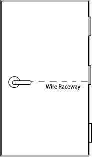
  • A means of getting current from the door frame into the device, such as a door cord or electric power transfer will be needed.
  • Voltage drop due to length of wire run could be an issue with high current inrush devices.

Following are examples of electric latch retraction exit devices by different manufacturers. 

Please keep in mind that any of the part numbers shown may change without notice at any time.  

Adams Rite

Adams Rite makes hardware primarily for aluminum-and-glass storefront type doors, but also for standard hollow metal and wood doors. All of their exit devices are available with MLR (motorized latch retraction) or solenoid latch retraction (EL for rim devices and LR for all other devices).  They make rim, concealed vertical rod, surface vertical rod, and mortise exit devices.

  • MLR motorized option draws 850 mA during retraction and 370 mA when maintained in dogged hold position at 24 VDC.  Available in 24 VDC only.  (ex. part number 8xxxMLR) 
  • EL solenoid driven option (for rim devices, example part number 8801EL-36-12) draws 1.5 Amps at 12 VDC and 600 mA at 24 VDC
  • LR solenoid driven option (example part number 8xxxLR-36) draws 16 Amps at 24 VDC (inrush) and 500 mA (holding current) at 24 VDC 

They do not offer a retrofit kit for field conversion of existing devices as of this writing, but aftermarket kits are available from other manufacturers.   

Falcon / Doromatic

Falcon makes Doromatic exit devices primarily for aluminum storefront doors. All of their touch-bar style devices are available with electric latch retraction. Currently they use the Von Duprin-type solenoid for latch retraction, and use the Von Duprin PS914-2RS power supply to handle the 16-amp inrush current these solenoids draw.

The PS914-2RS  will power up to 2 exit devices with electric latch retraction.

Doromatic offers a solenoid driven electric latch retraction field retrofit kit for their 1490 series concealed vertical rod and 1590 series rim devices as well as factory installed electric latch retraction. The EL1690 concealed vertical rod device and EL1790 rim device can be used field retrofit kits to electrify the 1990 and 2090 series crossbar “pipe-type” exit devices for latch retraction since they have the same latch side footprint and the vertical rod devices can use the existing rods.  

Falcon offers their grade 1 series 24 and 25 exit devices with electric latch retraction or motorized latch retraction and field conversion kits. 

Falcon exit device example part numbers: 

  • EL solenoid latch retraction (EL25-R-EO 3 US32D)
  • MEL motorized latch retraction (MEL25-R-EO 3 US32D) 

Example field conversion kits: 

  • ELK-3 or ELK-4 (or 650147 or 650148) solenoid latch retraction kit for 3- or 4-foot 24 or 25 series exit devices.  Specify finish. 
  • 25-MELK-3 or 25-MELK-4 (or 47266630 or 47266631) motorized latch retraction kit for 3- or 4-foot 25 series devices only.  24 series MEL devices are factory only.  Specify finish.  

Precision

Precision makes exit devices for hollow metal, aluminum storefront, and wood doors, fire rated and non fire rated. All of their touch bar-style exit devices are available with electric latch retraction, and they offer both solenoid driven and motorized electric latch retraction for their grade 1 devices.   

  • ELR solenoid latch retraction (ex. part number ELR2103 630 36)
  • MLR motorized latch retraction (ex. part number MLR2103 630 36) 

Precision makes retrofit solenoid electric latch retraction kits specific to various device characteristics.   

  • Non-fire rated 3- or 4-foot wide stile exit device:  ELRK-3 / ELRK-4 
  • Fire rated 3- or 4- foot wide stile exit device:  ELRKF-3 / ELRKF-4 
  • Non-fire rated 3- or 4- foot narrow stile exit device:  NELRK-3 / NELRK-4 
  • Fire rated 3- or 4-foot narrow stile exit device:  NELRKF-3 / NELRKF-4 

They make one kit to convert any of their touch bar devices to motorized latch retraction: 

  • RPMLR-K  

Sargent

Sargent offers a wide variety of exit devices in various functions and configurations to accommodate diverse applications. All 80-series models are available with “Remote Dogging / Latch Retraction”.  Sargent recommends the Securitron BPS-24-1 power supply, a simple 1-amp, 24VDC power supply, to power electric latch retraction devices.  

To designate Remote Dogging / Latch Retraction they use a prefix 56- to the exit device part number.

Example part number: 56-8810F 32D 

Sargent offers two kinds of retrofit kits to convert existing Sargent exit devices to motorized latch retraction in the field.  The R56A kit includes a complete touch bar (specify finish) whereas the M56A consists of a motor and control module unit that is unfinished.  Rail size (according to door width) must be specified for either.  Sargent uses letter designations for rail size: 

  • E = 24 to 32 inch door width 
  • F = 33 to 36 inch door width 
  • J = 37 to 42 inch door width 
  • G = 43 to 48 inch door width 

Example part numbers: 

  • Modular kit:  M56AF
  • Push Rail Assembly Kit:  R56AF 32D 

Von Duprin

Von Duprin offers two kinds of electric latch retraction in rim, surface vertical rod, concealed vertical rod, mortise, and three-point exit devices for narrow stile aluminum storefront, standard hollow metal, and wood door applications.  To order exit devices with latch retraction use prefix EL for solenoid latch retraction or QEL for motorized latch retraction.  

EL prefix devices require the PS914-2RS power supply.   PS902-2RS are the manufacturer’s recommendations for QEL prefix devices, but any regulated and filtered power supply 2 Amps or greater will do.  If powering 2 devices simultaneously, the PS902-2RS will stagger the inrush, firing one QEL at a time.  Since each draws 1 Amp, simultaneous activation of two devices might max out a standard 2 Amp power supply.  If another manufacturer’s power supply will be used to power two devices, I suggest using a 3 Amp power supply. 

Wire run/current drop factors apply.  

Example part numbers:  

  • Solenoid latch retraction:  EL99EO 3 26D 
  • Motorized latch retraction:  QEL99EO 3 26D 

Von Duprin offers a variety of retrofit kits to field convert existing exit devices to electric latch retraction.  Options include motorized latch retraction kits, kits that include rail backplate (specify door 3 or 4 foot door width), kits with motorized latch retraction and hex key dogging, etc.   Here I list part numbers for the most common variations:  

  • Solenoid Latch retraction (EL) kits:  
    • For 3-foot door width:  050070 
    • For 4-foot door width:  050078 
  • Motorized latch retraction (QEL) kits: 
    • For 3-foot door width: 958003 
    • For 4-foot door width:  040065 

Dorma

Dorma offers solenoid and motorized latch retraction for their 9000 series exit devices.   ES is the designation for solenoid driven latch retraction and MLR for motorized latch retraction.  They offer full replacement touch bar and rail assemblies that can be used to field convert devices to ES or MLR.   

Example exit device with latch retraction part numbers: 

  • With solenoid latch retraction:  9x00B RHR 630 ES 
  • With motorized latch retraction:  9×00 RHR 630 MLR 

ES option requires Dorma PS501 power supply.  

MLR option, Dorma DKPS-2A power supply recommended, but any 2 Amp regulated and filtered power supply will work.  

Rail size designations:  

  • A – for door width 34 inches to 48 inches
  • B – for door width 28 inches to 36 inches 
  • C – for door width 25 inches to 30 inches 

Touch bar and rail assemblies, example part numbers: 

  • MLR option motorized latch retraction:  MLRTBR 630 B
  • MLR option fire rated motorized latch retraction:  MLRFTBR 630 B
  • ES option solenoid latch retraction:  ESTBR 630 B
  • ES option fire rated solenoid latch retraction:  ESFTBR 630 B 

Wiring Through a Door

AKA coring the door or drilling a raceway.

Like Moses leading the Hebrews across the Red Sea, you must work a miracle to bring electricity from the hinge side of the door to the lock side.  Luckily it is a miracle on a much smaller scale.  Moses had to deal with millions of gallons of water and miles of sea bottom whereas you only have to deal with a few feet of wood.   So relax.

Raceway Reasons

The best way to get a wire raceway into a door is to order the door with it already built in.  This is especially true of hollow metal doors which often have cross members inside at angles to where the through-wire needs to go.  However, that would require planning in advance – a rare occurrence these days, it seems.    Lack of planning is the main reason that field-drilling a raceway becomes a necessity.

Coring the door is usually the best option whenever you are installing an electric lockset.  This is true whether you use a door cord or an electric hinge.  The safest place for the wire is inside the door.

You will probably also need to drill a raceway if you are using an electric strike in the inactive leaf of a pair of doors.   Usually you will also need a door cord, electric hinge or other power transfer.

Horizontal vs. Vertical

Electric Through-Wire Hinge

It is possible to drill a raceway with the door still up.  I have done it but I don’t recommend it.  It takes nerves of steel and a stiff, sharp drill bit.  You need a decent sized bit that won’t bend right or left on you as you try to drill straight, and you need to make sure that the door doesn’t move on its hinges while you are drilling.

I found that taking the door down and standing it on edge in a homemade door stand is the easiest for me because:

  • The door is much less likely to move while you are drilling it
  • Using a level to guide you is much easier, and
  • Gravity is on your side

Constants

Certain constants apply to either horizontal or vertical drilling.  In both cases I recommend a 3/8-inch by 3-foot drill bit.  If the door is more than 3 feet wide, drill it from both sides or get a 4-foot bit.  I prefer to drill from both sides because it’s a lot easier to drill straight for 18 or 24 inches than it is to drill straight for 3 or 4 feet.

Simple Door Stand

If you have a drill with a built-in level, use it.  If your drill does not have a built-in level, any level will do.  Just put it against the door anytime you want to check the angle at which you are drilling.  Determine if the door has a beveled edge and don’t let the bevel skew your path through the door.  Make sure your drill bit remains parallel to both the interior and exterior surfaces of the door.


Drilling a raceway across a door is a challenge, but all it really takes is good focus and an ability to drill a straight hole.  If you are challenged in the latter aspect, you might consider a drilling tool like the Security Door Controls product shown below.   If you have many raceways to drill, a tool like this one is a great idea.

Security Door Controls 7000IDF Door Drilling Kit


Exit Device, Panic Hardware and Crash Bar Basics

Introduction

The terms “crash bar”, “panic hardware” and “exit device” all mean the same thing.

Precision Apex 2000 Series Rim Exit Devices by Stanley

Exit devices are used on doors in the path of egress in buildings built to accomodate numbers of people.  Facilities like schools, hospitals, goverment buildings and large residential buildings all use them.  Fire rated exit devices are used on fire rated doors.  Most interior doors that require exit devices, especially stairwell doors, are fire rated.

Fire Rated Exit Devices

Fire rated openings require fire rated exit devices. Fire rated devices are so designated by Underwriters Laboratories. I am told that UL tests them by mounting the device on a fire rated door and setting the door on fire, letting it burn for a time, and then blasting the door full blast with a fire hose. If the door opens, the device fails the test and cannot be sold as a fire rated exit device.

Non-fire-rated exit devices are used mainly on exterior doors.

Dogging Feature

One of the chief differences between a fire rated exit device and a non-fire-rated exit device is called the “dogging” feature. A dogging feature allows the user to “dog the bar down” using a hex wrench or standard key, leaving the door unlatched. Since fire rated devices must always postitively latch, they never have a dogging feature.

Narrow Stile Exit Devices

The term, “lock stile”, refers to the part of a panel door or aluminum-and-glass storefront door onto which an exit device or other lock is installed. Many aluminum storefront doors one encounters in the world have lock stiles only 1-3/4 inches to 2 inches wide. If you need an exit device for such a door, you need an exit device for a narrow stile application.

Exit Device Types

The four main types of exit devices are:

  • Rim
  • Mortise
  • Surface Vertical Rod
  • Concealed Vertical Rod
  • Mid-panel

See examples of rim exit devices at:

http://www.sargentlock.com/products/product_overview.php?item_id=86

and

http://www.sargentlock.com/products/product_overview.php?item_id=57

See an example of a surface vertical rod device at:

http://www.sargentlock.com/products/product_overview.php?item_id=56

See an example of a mortise exit device at:

http://www.sargentlock.com/products/product_overview.php?item_id=59

See an example of a concealed vertical rod exit device at:

http://www.sargentlock.com/products/product_overview.php?item_id=60

Specifying Exit Devices

Exit device choice is based upon the door. As mentioned previously
if the door is fire rated, the exit device must also be fire rated.
If the door is a narrow stile door, an narrow stile application exit
device is required.

In addition, you need to know the width of the door. Exit devices
come in different lengths to accomodate different door widths, so
that the touchpad of the exit device provides the coverage required
by national and local life safety and/or fire code. Door thickness
could also be a factor, especially if you are going to need exit device
trim, that is, a lever, doorknob or thumbpiece that allows people
to unlatch the door and enter from the outside. I will discuss exit
device trim shortly.

For a pair of doors (otherwise known as a double opening, or a set
of double doors), the best choice is usually a surface or concealed
vertical rod exit device. In this case you also need to know the door
height.

It is possible to lock a pair of doors using one rim or mortise exit
device and either a vertical rod exit device or a set of flush bolts,
but these solutions (while perhaps saving a little money) present
other problems. If you use a rim device on the active door, then the
strike (the part you will be mounting on the inactive door to receive
the latch of the rim device) is called quite appropriately a “pocket-ripper”
strike, since it hangs into the opening at pretty much trouser pocket
level. Use of a mortise exit device on the active leaf eliminates
that problem, but it will not work as reliably as would two vertical
rod devices, and would save very little money.

The choice between concealed and surface vertical rod exit devices
should be a simple one. If you are having doors made, have the door
manufacturer install concealed vertical rod exit devices at their
factory. If you are installing a vertical rod device at a job site
on existing doors, then use surface vertical rods.

Concealed vertical rod exit devices are preferable because they are
protected from damage by the door. However, it is an especially skilled
installer who can install one in the field, and at that, it is a time
consuming and difficult job.

Mortise exit devices offer superior durability, and are otherwise
the best choice when retro-fitting an exit device to an existing door
that already has a mortise lock.

Exit Device Trim

The exit device goes on the inside, or interior side of the door,
and exit device trim goes on the outside. Exit device trim is available
in different functions. Below are the most common functions:

  • Key locks and unlocks lever handle or thumbpiece. Trim can be
    left unlocked for periods of time allowing free entry.
  • Key retracts latch. Exit device is always locked from outside,
    entry by key only. Not available on some vertical rod exit devices.
  • Key unlocks trim only while key is inserted. User turns key, operates
    control for entry. Trim is relocked when user removes key.
  • Passage function: trim is always unlocked allowing free entry.
  • Dummy trim: trim is rigid, usable as a handle to pull the door
    open when either the bar is dogged down using the dogging feature
    (see above) or when the latch is retracted or the device released
    by other means.

Exit Device Options

Exit devices are available with a wide variety of options that increase
their functionality. These include:

  • Alarm
  • Touchpad or latchbolt monitoring switches
  • Electric latch retraction
  • Electric dogging
  • Delayed egress


When Your Key Won’t Turn

Someday you might come home or go to open up your business and find that your key won’t turn at all, not even a little. There are several reasons this might occur.

At right, illustrations show the operation of a standard pin tumbler lock. When you insert your key, the key raises the pins to the point where the division between the top pins and the bottom pins aligns with the division between the plug and the bible of the cylinder, allowing the plug to turn.

Sometimes dust and dirt collect inside the lock cylinder. When that happens the dirt can cause the pins to stick in a partially raised position, preventing the plug from turning. In most cases a spritz of dry lubricant will be sufficient to free up the plug and allow you to open your door. Simply spray the lubricant into the keyway and insert the key a few times to work the lubricant into the mechanism. If this method does not work you may need to use a more solvent-based lubricant like WD-40 to loosen the dirt. Locks exposed to the elements sometimes collect a lot of dirt.

If your key will only go in part way, this could still be the same problem, or there may be an obstruction in the keyway. Illumination of the keyway reveals that the bottom pins hang down into the keyway. In the event that lubricating the lock is ineffective, slide a thin piece of wire into the lock along the bottom of the keyway, avoiding the pins, and feel for an obstruction. If the piece of wire will not go in as far as the length of the blade of your key, there may be an obstruction present. At this point you might want to call a locksmith, however, you can gently work your way past the pins and try to go over the obstruction in order to try to coax it out. This process can take a lot of patience and skill, and it is possible to make the problem worse if you are heavy handed with the pins.

From Wikipedia
Should lubrication fail to free up your lock and you can find no obstruction, your lock may have a more serious malfunction, such as a pin chamber worn enough to allow a pin to get stuck at an angle, or a corroded pin that is frozen in place and will not budge no matter what. In these cases you need a professional to gain entry for you and repair your lock. If you succeed in freeing up your lock but find that the problem is reoccurring with increasing frequency, it’s probably time for you to replace your cylinder.

Door Problems

If the space between the door and the frame is different at the top than it is at the bottom, you've either got a door problem, or you're going to have a door problem.
As a locksmith I was called many times to fix what the customer thought was a lock problem only to find that the problem was with the door, not with the lock.   “What’s the difference?” you may well ask, proving to me that you are no locksmith.  “Well,” I would smugly reply, relishing my brief moment in the spotlight of useful knowledge.  “I’ll tell you.”  And I will, too.

Overview

Hardware and doors age together and develop different and sometimes incompatible symptoms of aging.  Like people, doors are subject to the prolonged effects of gravity.  Things start to sag, and for a while you can tighten things up and slow down or even perhaps reverse the effects, but eventually Newton will have his way and what was put up will come down.  That is to say the door, suspended an eighth of an inch (ideally) above the threshold, will eventually come to rest on that threshold.  If left to the ravages of time it will eventually cut a groove in the threshold.

Locks, meanwhile, start having trouble finding their strikes.  (A strike is to a lock what a tunnel is to a train or the side pocket to the eight ball.)  Usually (but not always) the strike stays put, but the lock travels downward along with the lock side of the door.  Eventually the lock may not line up with the strike at all, but before that there will be friction between the bolt or latch and the strike, making the lock difficult and eventually impossible to lock and/or unlock.

Besides sagging, wooden doors may warp and door frames of any construction may move as the building shifts and settles over time.  These changes may also result in locks that no longer line up and do not work properly.

Diagnoses and Remedies

The Sagging Door

Looking at the closed door from the ‘pull’ side, it is often easy to see if it is sagging.  If the jamb has not moved and was installed correctly, it is perfectly square.  Ideally there will be a one eighth inch gap between the top and the left and right edges of the door and the frame.  If the door hangs at an angle to the frame, it is probably sagging.

Marks on this ANSI 4-7/8 strike plate show that the latch has traveled down as it has traveled through time because of gravity.

If a door is sagging enough, there will be marks on the lock edge of the door where it is rubbing against the frame.

Often this is because the top hinge is loose.  If you tighten all the hinge screws this may solve the problem.  On a wooden door and/or frame you may find that the screws for the top hinge are stripped – that is, the screw hole has become enlarged because the weight of the door has pulled the screw out.  The solution for this situation may be longer screws.  Be sure you replace the screw with one of the same wire size so it fits flush in the countersunk screw hole of the hinge.  Commercial hinges use a size 12 screw, but bring one of the screws to the hardware store to match it up if you have any doubts.

Many times longer screws do not solve the problem because the wood door is not solid would, but particle core or gypsum core, or the frame is shimmed out from the studs so far that that there is nothing for a screw less than five inches long to grab.  In this case it might be necessary to relocate the top hinge (not generally a good result), install an additional hinge or hinges above and/or below the existing top hinge, install a reinforcing pivot hinge at the top of the door, or replace all the hinges with a continuous hinge.

Damaged Hinges and Crooked Door Jambs

If hinge tightening does not solve the problem, the hinge or hinges may be bent or the door frame may have shifted.

Hinges are often bent when someone (who is not too bright) places a piece of wood between the door and the frame to hold the door open.  It is possible to bend a hinge back to almost its original shape, but when it is bent the metal of the hinge is fatigued and it will never be the same.  Since hinges vary by manufacturer, it is best to replace all the hinges if one is bent unless you can find an exact replacement for the bent hinge.

If the hinges are neither loose nor bent, the door frame may be out of alignment.  Use a carpenter’s square to check the corners of the frame and a level to check the legs and header.

If it is a three-piece, knock down hollow metal frame in a sheet rock wall, you may find an adjustment screw at about eye level on each leg of the frame.  These vary widely between door manufacturers, so see what kind of driver may be required to turn the adjusting screw.   You can experiment with the adjusting screw to see if turning one or the other either way has any desirable effect.  Sometimes the adjustment screws are not connected to anything that has contact with anything else.  In that case turning the adjustment screws will have no effect.

Hollow metal frames that are installed in interior sheet rock walls are often secured to the wall at the bottom of each leg with a screw.  If the floor has shifted beneath the frame so that one leg is now lower than the other, it is possible to remove the screws from both sides of the leg, gently pry the leg up off the floor a little and insert shimming material beneath the leg to hold it up.

Wooden Doors and Frames

Wooden doors and frames are generally susceptible to more movement than hollow metal.  In addition to sagging, there is warping, twisting and swelling that may occur.  Fortunately whenever finished wood rubs up against something, it tends to leave a mark.  These marks can tell you what the door is up to and help you fix the problem.

Unlike a hollow metal or Fiberglas door, you can plane a wood door down.  Careful, though:  make sure you iron out any hinge problems before you start to plane, otherwise you’ll plane, the door will sag more, you’ll plane some more, the door will sag some more – pretty soon you’ll have a big space between the frame and the door someplace and you won’t need a door viewer anymore because you’ll be able to see out the crack.

One has no choice but to plane a door that has swollen.  Plane carefully, a little at a time, and do your best to keep the door as square as possible.  After planing, finish the door with paint, polyurethane or varnish – especially the edges – so that it doesn’t swell again so fast.

This is not a complete list of door problems, but it is a good sampling.  I hope it serves as a starting point for you to solve your own.

Fail Safe and Fail Secure Electric Locking Devices

Definition

Basically:

  • Fail Safe = power off, it’s unlocked
  • Fail Secure = power off, it’s locked

Electric locking devices include:

  • Electric strikes
  • Electromagnetic locks
  • Electromechanical locks
  • Electrified exit devices

Most electric strikes are sold fail secure by default. For example,
if you order a Von Duprin 6123 24V US32D, and architectural grade 1
electric strike, it will most likely come fail secure regardless if
it has Von Duprin’s “FSE” (standing for fail secure) in the part number
or not. The part number in the Von Duprin price book does not include
“FSE.” To be sure you are going to get a fail safe electric strike (not
the norm) if that is indeed what you want, in this instance you would
include Von Duprin’s abbreviation for fail safe, “FS”, for example,
6123 -24V-FS-US32D.

All electromagnetic locks are fail safe because they are always
unlocked when disconnected from the power source. Using a battery
back-up does not make an electromagnetic lock fail secure because
the magnet would still be unlocked if the power was disconnected.
Later in this article it should become apparent why this detail
is important for reasons of life safety.

Electromechanical locks include standard cylindrical or mortise
locks that have been electrified and locks that are designed to
only work electrically, such as an electric bolt lock. They are
sold in equal amounts fail safe and fail secure.

Electrified exit devices come in a variety of functions, including
those with electric latch retraction and those with electrified outside
trim control. Electric latch retraction devices are fail secure whereas
exit devices with electrified exterior trim control might be either
fail safe or fail secure.

Application

Electric Strikes

Fail safe electric locking devices are used wherever doors must remain
unlocked in the event of a fire or other life safety emergency. If
the opening is fire rated, it must be positively latched by a fire
rated device in the event of a fire. Therefore there is no such thing
as a fire rated fail safe electric strike because if the power were
off (as it might very well be during a fire) the door would not be
positively latched. If you install a fail safe electric strike on
a fire rated opening, the inspector can require you to replace the
entire doorframe.

Technically, fire rated door frames cannot be modified in the field,
but must be prepared for hardware (including architectural grade electrified
hardware) in a fire rated shop. I have never heard of this being enforced,
nevertheless, the AHD (Authority Having Jurisdiction) could enforce
it, so if you plan to modify a fire rated opening in any way it might
be a good idea to get the local fire marshal on board during the planning
stages.

In general, a fail safe electric strike is a good choice for a “non-fire-rated
door that must be unlocked in the event of an emergency other than
a fire” kind of application.

Fail secure electric strikes are a good choice for exterior or other
non-fire-rated doors where remote release or electronic access control
is needed. They are pretty reliable, usually not difficult to install,
and relatively inexpensive. One of the chief disadvantages of an electric
strike is that, on out-swinging doors, they provide an opening into
which a burglar can insert a tool, such as a tire iron, to pry directly
on the locking device. A latch guard is a minimally effective deterrent
to this kind of attack.

(Exterior doors are almost never fire rated, and if they are, usually
it is because all the doors on the job were ordered to the same spec,
not because they have to be.)

Electromagnetic Locks

Some inspectors and fire marshals just don’t like electromagnetic
locks. This is another reason to get your local AHD on board from
the start. But if your AHD is not an obstacle, a mag can be a good
solution for existing fire rated doors with existing fire rated hardware
on them. The fire rated hardware can stay to keep the door positively
latched in the event of a fire, and the mag is inherently fail safe,
so it could be a good choice for stairwell doors, greatly simplifying
the application. The problem with mag locks is that they lock both
sides of the door simultaneously. That means you have to deal with
both a means to get in (access control) and a means to get out (presence
detector and redundant exit pushbutton, for example).

If the door already has an exit device, it is probably possible to
install a request-to-exit (RX) switch in the bar to allow exit by
a fully mechanical means – a factor which might make the AHD happier
with the installation. The AHD will also want to know that all electromagnetic
locks are wired so that the fire alarm will cut power to them in the
event of a fire.

Since a mag lock does not positively latch, it cannot be legally
used alone on a fire rated door. There must be a fire rated positively
latching mechanism in addition to the mag.

Delayed egress electromagnetic locks can also be used for access
control on egress doors while helping to prevent unauthorized exit.
For more information on delayed egress, please visit:

Electromagnetic locks are not too expensive and are very easy to
install. Because they are inherently fail safe, you may want to install
a battery back-up system so that they remain locked during routine
power outages.

Electromechanical Locks

Fail safe electrified standard locks are ideal for stairwell doors
(unless they already have exit devices) because they remain positively
latched when unlocked. Many states and localities require that stairwell
doors be unlocked in the event of a fire, and because all interior
stairwell doors are fire rated, they must also remain positively latched.

In order to replace a standard mechanical lock with an electrified
one, a raceway must be drilled through the door from lock side to
hinge side so that wire can be run to power the lock. If you guessed
that, technically speaking, this voids the fire rating on a fire rated
door, you were correct. Be sure to clear all modifications to fire
rated openings in advance with the local AHD.

Electric bolts are usually used as a last resort when no other application
will work, such as when retrofitting access control to automatic sliding
doors. Electric bolts are most commonly used in prisons, where egress
concerns are treated rather differently than commercial applications.
They can also be used in place of electromagnetic locks, however electric
bolts designed for commercial (rather than detention) applications
are less secure, less durable and more difficult to install than mag
locks.

Electrified Exit Devices

If a door has an existing exit device or an architect has specified
an exit device for an opening, it is because the capacity of the building
in terms of the number of people therein warrants the use of an exit
device. Therefore it is unwise to replace an exit device with another
kind of hardware.

Luckily, many exit devices can be electrified in the field either
by replacing internal parts of the device or by adding an electrified
trim (outside handle or lever).

As I mentioned earlier, exit devices can be electrified in one of
two ways:

  • Electric latch retraction
  • Electrified outside trim

Since electric latch retraction is always fail secure, it might not
be a good choice for stairwell doors unless it was always unlocked
from the stairwell side. If that were the case, the only probable
purpose for the electric latch retraction would be to unlatch the
door for a power operator (automatic door opener).

Electric latch retraction is ideal on exterior pairs of doors where
fail secure access control is required. Since exterior pairs of doors
are often equipped with concealed vertical rod exit devices, installing
electric latch retraction is often the easiest and best alternative.
Electric latch retraction (or electric remote dogging) is also very
compatible for use with power operators.

The down side of electric latch retraction, in addition to being
expensive in its own right, is that it often requires a special and
expensive power supply. Sargent 56 prefix exit devices are an exception,
requiring only a minimal power supply for activation.

Fail safe electrified exit device trim is a good alternative for
stairwell doors whether they already have an exit device or not. For
one thing, since the wire powering the trim is run through the exit
device, no modification of the fire rated door is necessary.

Electrified exit device trim is also available fail secure, and is
often a less expensive alternative to electric latch retraction where
simple access control is the goal.

Note on “Continuous Duty”

I have been asked, ‘What is the difference between fail safe and
continuous duty?’ Fail safe applies to the function of the device
as described above whereas continuous duty simply means the strike
is built to be constantly powered if so required. The confusion arises,
I think, because all fail safe locking devices are continuous duty.
This is because a fail safe device must have power to be locked. Fail
secure electric strikes that are connected to a timer and powered
all day to remain unlocked also must be continuous duty rated. Therefore,
not all continuous duty electric strikes are fail safe, but all fail
safe strikes are continuous duty.

Rule of thumb: almost every kind of electric locking device that
runs on DC current is continuous duty.

Hinge Basics ‐ Architectural and Residential Hinges

A huge variety of door hinges are available in today’s commercial hardware market. Which hinge is right for your application? This article discusses hinge types, hinge characteristics, and basic guidelines
on how to choose a hinge for your application.

Parts of a Hinge
At right is an illustration that details the components of a full mortise hinge. Pictured is the most common hinge used in the United States, a five knuckle, full mortise ball bearing architectural grade template hinge, four-and-a-half by four-and-a-half inches.

  • The leaves are fastened to the door and door frame.
  • The bearings keep the hinge aligned help the hinge last longer by reducing wear
  • The pin (shown slightly withdrawn from the knuckles as if being removed) holds the leaves together and provides the axis on which the door will turn
  • The knuckle is a loop of metal through which the pin passes
  • The top tip rests on the top knuckle of the hinge, stabilizing the pin; the bottom tip is attached to the bottom knuckle and helps keep the interior of the knuckles clean.

Some Variations

The leaves could be of equal widths, or unequal; the leaves could be “swaged”, meaning bent to compensate for a door with a beveled edge; the bearings could be ball bearings, concealed bearings, lube bearings, or “plain bearings”, indicating no bearings at all; the pin could be non-removable or fixed; there could be five knuckles, three knuckles, or in some cases, no knuckles; and hinge tips could be decorative or could serve a purpose, such as hospital tips, which are beveled to prevent things from getting caught on them.

Commercial architectural grade hinges could be standard weight or heavy weight; they could have square corners or round; and they could be “template” or “non-template” hinges, indicating whether its screw pattern matches architectural conventions so as to fit in standard hollow metal door preps or not.

Electrical options are also available, such as electric though wire, concealed magnetic contact, exposed electrical contact, and others.

Hinge Sizing

To measure a full mortise hinge, also called a butt hinge, lay it on a flat surface.  Measure the height, then the width.  When you specify full mortise hinge sizes, always refer to the height first, then the width.

Heavy Weight vs. Standard Weight Hinges

Heavy weight hinges are used for very heavy doors or doors that are subjected to very high traffic. Hinge “weight” actually refers to hinge leaf thickness. Heavy weight hinges leaves run closer to .200 gauge thickness, while standard weight hinges are more in the range .150 gauge thickness.

Hinge thickness is also dependent on hinge size. For example, a standard weight hinge 6 inches by 5 inches will be thicker than a standard weight hinge that is 4-1/2 by 4-1/2 inches.

Wide Throw Hinges

At right is shown a wide throw full mortise hinge. Wide throw hinges enable a door to open 180 degrees when a decorative door molding might otherwise prevent it from doing so.

Other Types of Hinges

All the hinges lifted below are available in standard weight and heavy weight versions for different commercial applications. Illustrations at right show various kinds of hinges.

Full Mortise Hinges

As I said earlier, full mortise hinges are by far the most common type of hinge. They come in a wide variety to accommodate diverse applications.

Half Mortise Hinges

Half mortise hinges are hinges that have one leaf mounted to the visible front of the frame and the other leaf mounted in a hinge prep, or mortise, on the edge of the door.

Half Surface Hinges

Half surface hinges are hinges that have one leaf mounted to the surface of the door and the other leaf mounted into a hinge prep on the jamb part of the door frame.

Full Surface Hinges

Full surface hinges have both leaves visible when the door is closed. One leaf is fastened to the surface of the frame and the other to the surface of the door.

Swing Clear Hinges

Swing clear hinges are designed so that when the door is opened to 90 degrees, the door itself is completely out of the opening.  For example, if you needed to move a cart through a door that was 35-1/2 inches wide through a 36inch wide door, unless the door was hung on swing clear hinges, you would have to be able to open the door 180degrees in order to get the cart through the opening.

All of the hinges above are available in swing clear versions.

Template and Non-Template Hinges

“Template” hinges are full hinges that have a standard screw pattern and sizing to fit into an ANSI  standard hinge prep, usually on a hollow metal door and frame. Most architectural (commercial) grade hinges are template hinges. Most residential hinges are non-template hinges.

Radius Corners

Radius corner hinges are hinges with rounded corners. “Radius” refers to the radius of the circle thatwould exist if the curve of the rounded corner were continued to form a circle.Architectural hinges are available with 1/4-inch radius corners whereas residential hinges are available in 1/4-inch radius and 5/8 inch radius corners.

Residential Hinges

Residential hinges are very similar to architectural hinges, but there are differences. As stated above, more often residential hinges are non-template hinges, but they are sized the same as architectural hinges. Residential hinges also more often have radius corners than architectural hinges and are usually made of thinner gauge metal. Often one will see an architectural grade hinge used on exterior doors and residential grade hinges used on doors within the dwelling.

Spring Hinges

Spring hinges are architectural hinges that are spring loaded so as to shut the door. They are available in fullmortise, with or without radius corner, in most sizes in which other full mortise hinges are made, and are available in template and non-template versions. A full mortise spring hinge is shown at right.  Beneath the full mortise spring hinge is a picture of a double acting spring hinge for a door that swings both ways.

Continuous Hinges

Continuous hinges are hinges that extend the full height of the door. They are widely used on aluminum storefront and hollow metal applications. They are a good alternative for high traffic applications where added durability is necessary. Continuous hinges are available in aluminum, steel, or stainless steel, and, like architectural hinges, are available in different types to accommodate different conditions. Many of these configurations match those discussed in this article.

Pivot Hinges

Pivot hinges are used on heavy doors in high traffic applications and on many aluminum storefront doors.  Since the weight of the door rests on the bottom pivot, the door does not “hang” as it does with other types of hinges, therefore there is less risk that the door will sag over time.  At right is a picture of a pivot set from Rixson Hardware’s pivot catalog.

Electrified Hinges

Full mortise, pivot, continuous hinges and others are available with electrical options such as:

  • Electric Through Wire:  a number of conductors are threaded through the hinge in order to conduct electricity from the door frame into the door (or vice versa) to power electric locks or transmit contact closure from monitor switches in the door or in the locking hardware. Available with anywhere from 2 to12 conductors, typically 24 gauge wire. 2conductor,18 gauge wire is also available.
  • Concealed Magnetic Contact: a magnetic contact reed switch is concealed in the leaves of a full mortise hinge. When the door is opened, the leaves are spread apart, breaking or making the contact. HInges with concealed magnetic contact are handed.It is possible to have both the above options in the same hinge.

Non-Removable Pins

In situations where you have an out-swinging secured door, you can use hinges with non-removable hinge pins. Non-removable hinge pins are pins which have a groove milled in them in the middle. A set screw is threaded through the middle knuckle to mate with the groove (see picture at right) to inhibit burglars from pulling the pin and the door to gain entry.  (In the picture, the center knuckle is not shown so that theset screw can be seen.)