You are currently browsing the archives for the builders hardware category


Full Height Housings for Electromagnetic Locks

Maglocks are generally great problems solvers, but they also create problems.  One significant problem is the fact that they are usually installed on the header, and therefore only lock the top of the door.  If the only lock on the door is a magnetic lock and the door is fairly flexible, a reasonably strong person may be able to pull the bottom of the door open four or more inches.

One solution to this problem is to install mags top and bottom on the lock side leg of the frame rather than on the header.  If you have an opening that measures at least 35 inches from stop to stop and you use magnets that are three inches wide or less, you can install mags in the opening and still have 32 inches clear to comply with the American Disabilities Act.  The problem with this idea is that no matter where they are installed in the opening, users are likely to bump into them with some body part or other.

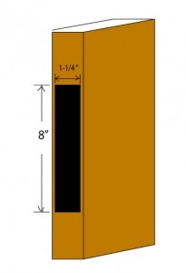
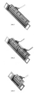
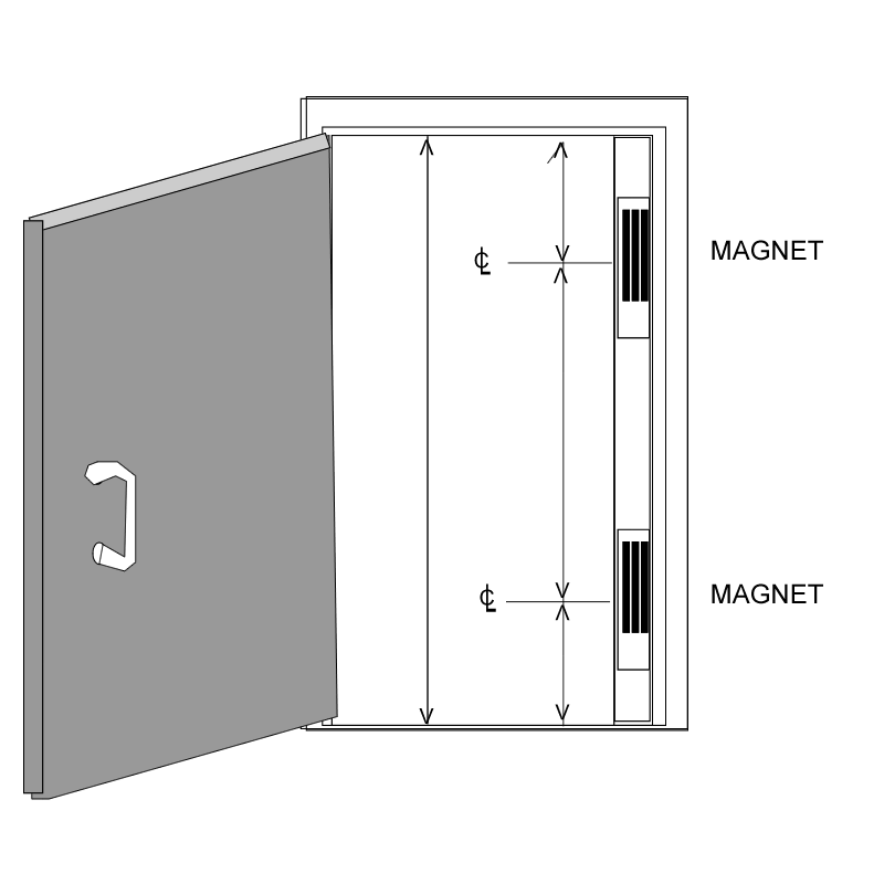
Enter the full height housing for electromagnetic locks, an enclosure that houses one or two maglocks and mounts on the stop of the lock side leg of the door jamb as illustrated below.

The illustration above is one I prepared for a customer so that I could order a custom built, full height housing for two electromagnetic locks.  The drawing shows the dimensions I requested as indicated by the lines with arrows at both ends:  height of the opening from threshold to header stop; distance from header stop to center line of upper maglock prep; distance from threshold to center line of lower mag prep; and distance between the center lines of the mag preps.

Provided the opening is at least 35 inches clear and the housing is no more than three inches wide, the opening will still comply with ADA after the full height housing system is installed.


Exit Device Checklist

See also Exit Device Basics

Here are a few questions you need to be able to answer before you order exit devices:

  • Is the door made of wood, hollow steel, Fiberglas, aluminum and glass, or all glass?
  • Is the door is fire rated or non-fire rated?
  • Door width if single door or pair of doors with center mullion?
  • Door width and height if for a pair of doors without mullion?
  • Door thickness?
  • Exit device finish?
  • Will this be an exit-only device, or will there be outside trim?
  • If there is outside trim, what function is it?

It will save you time and aggravation if you know the answers to these questions before you call your hardware vendor.

You may also want one or more of these or other mechanical options:

  • Cylinder dogging (not available on fire rated devices)
  • Less bottom rod (for vertical rod exit devices)
  • Double cylinder (trim locked or unlocked from inside secured space)

There may also be electrified options:

  • Does the exit device need to have electrified trim?  If so, fail safe or fail secure?
  • Does the exit device need to have electric latch retraction?
  • Does the exit device need to have push pad or latch monitor switches?
  • Do you need a delayed egress exit device?

Save time and money by gathering the necessary facts before shopping for exit devices.

Interconnected Locks


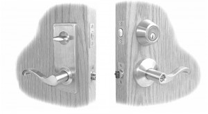
Sargent 7500 Series Interconnected Lock

An interconnected lock is actually two locks that are connected by an assembly that retracts both the deadbolt and the latch simultaneously when the inside handle is turned.   This is done to fulfill the life safety requirement under NFPA 101 that egress should be accomplished by one motion with no prior knowledge necessary, and at the same time provide the user with the security of a deadbolt.  The same function could be provided by an entry function mortise lock, but interconnected locks are cheaper, since they are usually cobbled together out of (usually) a grade 2 cylindrical lock and a tubular deadbolt.

The history of the interconnected lock is a twisted, strange story of different companies reinventing the wheel with different distances between the centerlines, connected or separate latch/bolt assemblies with correspondingly different strike preps, and radically different hole patterns on both interior and exterior door surfaces.  The end result has been many, many doors and frames prepped for locks that are now irreplaceable.

Today, preps are much more standardized.

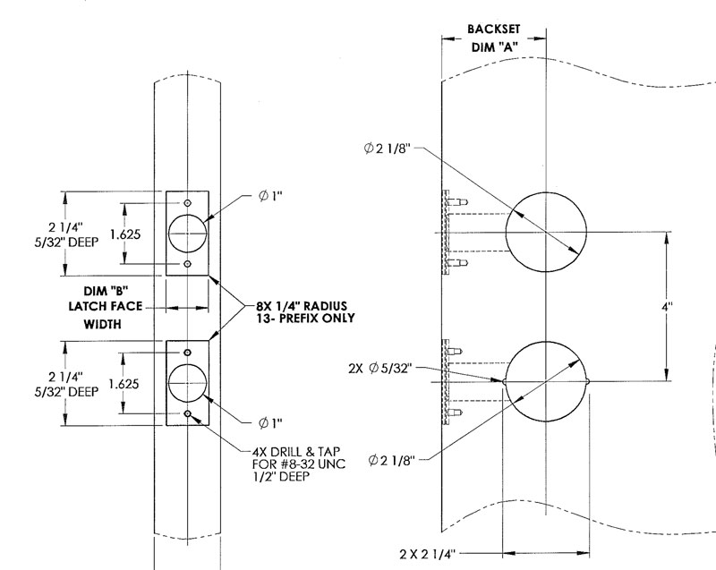
These are some of the interconnected locks available today and the measurements of their preps:

  • Falcon H Series – 4 inches CTC, 1-3/4 inch hold above, 2-1/8 inch hole below
  • Schlage H Series – 4 inches CTC, 1-1/2 inch hole above, 2-1/8 inch hole below
  • Schlage S200 Series – 4 inches CTC, 1-1/2 inch hole above, 2-1/8 inch hole below
  • Schlage CS200 Series – 4 inches CTC, 2-1/8 inch holes above and below
  • Sargent 75 Series – 4 inches CTC, 2-1/8 inch holes above and below
  • Yale 4800LN series – 4 inches CTC, 2-1/8 inch holes above and below

Replacing any of the locks above with any of the others would not present an enormous problem.


Sargent 7500 Series Door Prep

The “Passage Set”

Often, when customers say they want a “passage set” they really want a cylindrical lock that actually locks.  This is because they don’t know (and often don’t want to know) cylindrical lock functions.   Therefore, the next question I ask is often, “How do you want this ‘passage set’ to work?”

Of course, “passage set” is the name of a cylindrical lock function.  The function of a passage set is that the latch can always be retracted by turning either handle.  It always latches but is never locked.   So when customers order a passage set with an electric strike, I am doubly suspicious.  Do they really want a passage set with that electric strike?

Passage sets are used in non-locking applications like corridors, closets and some offices, and in non-locking fire rated doors to meet the positive latching requirement for fire rated openings.

Therefore, if you want to sound intelligent as you order your cylindrical locksets, don’t call them passage sets unless they are.  Thank you.


Deadbolts and Auxiliary Deadlocks

Overview

There are three main types of deadbolts:

  • Tubular (or Cylindrical)
  • Rim (surface mount)
  • Mortise

This article discusses the installation details and relative merits of each, as well as what to look for in terms of quality and security.

Deadbolts are usually considered an auxiliary lock because, with the exception of aluminum and glass storefront doors, they are not the primary means of latching the door shut.

Tubular Deadbolts

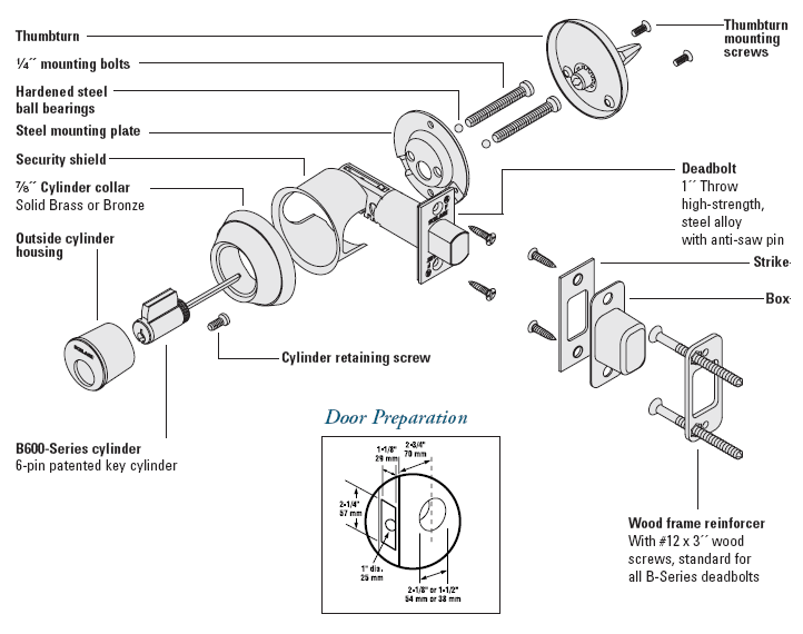
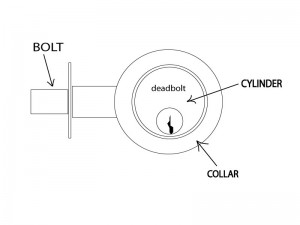
Above is a the first page of the B600 Series section of the Schlage commercial price book, showing an exploded view of the B600 series deadbolt.  Notice the “Security Shield” that protects the bolt from attack through the door.

Tubular (or cylindrical) deadbolts are by far the most popular deadbolts used today.   Preferred by renovation contractors for their ease of installation, they differ greatly in quality and security.

Installation

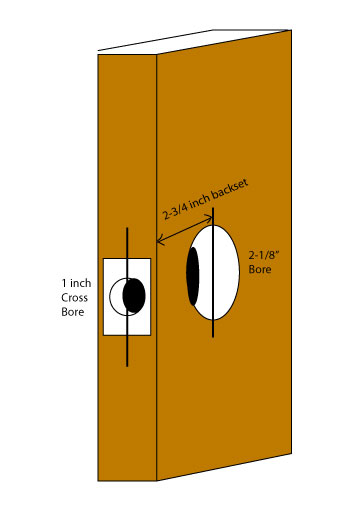
Tubular (or cylindrical) deadbolts are generally installed into a modified 161 door prep – that is, the same prep that accepts a standard cylindrical doorknob or lever set.  The 161 prep consists of a 2-1/8 inch diameter hole drilled through the door.  This hole is called the “bore.”   A second hole, called the “cross bore,” is then drilled from the lock edge of the door to intersect with the bore.  This second hole is usually 7/8 or 1 inch in diameter and is located on the center line of the first hole.  See diagram:


Quality and Security

Quality in tubular deadbolts ranges from the relatively poor quality of inexpensive locks widely available in lumber yards and hardware stores to high security versions available mainly from locksmiths and other security hardware specialists.  The differences between cheap and good are:

  • Sturdiness of the bolt
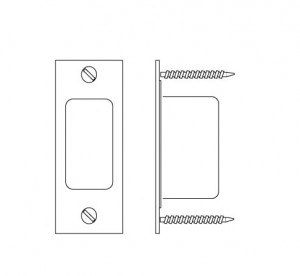
  • Strike reinforcement
  • Guarding of the bolt
  • Sturdiness of the cylinder collar
  • Bump, pick and drill resistance

The bolt is the actual part that projects out of the door and into the door frame.   The sturdier it is, the harder it will be for a burglar to break it off or saw through it.

The strike, or strike plate, is the rectangular piece of metal in the door frame that receives the bolt.  In a wooden frame, this piece will only be as strong as the wood it is attached to.  This is why it is important that the strike fasteners are long enough to reach the stud behind the frame.

The dust box goes inside behind the strike plate, inside the door frame.  A metal dust box makes it much more difficult to get a tool behind the end of the bolt – a very important function in terms of burglary resistance.

On a steel door frame the strike plate becomes less important, but it is still important to guard the end of the bolt as effectively as possible.

The cylinder collar is the washer-like ring that surrounds the cylinder and rests against the exterior surface of the door.   The best deadbolts have solid collars that spin freely if one tries to twist them off with pliers.   Cheap deadbolts have hollow collars that crush like a beer can when gripped by pliers.

Since key bumping videos are now widely available via the Internet, it is worthwhile making sure your locks are bump resistant; lock picking is more of an art, but some burglars are skilled in it, so pick resistance is worth having; and because cordless drills are inexpensive and readily available, drill resistance is a good thing, too.   Locks that are resistant to these three kinds of attacks have a UL Listing UL437 for Burglary Resistance and say so on their labeling.  Two deadbolts that offer UL437 burglary resistance as well as sturdy bolts, collars and provisions for strike reinforcement are the Schlage B600 series with Primus or Everest UL437 cylinder, and the Medeco D11 series with M3 series cylinder.

Rim Deadlocks

The terms “deadlock” and “deadbolt” are often used interchangeably.

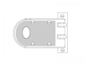
Surface mounted deadbolts, AKA rim deadlocks, were once the industry standard.   Many locksmiths’ fortunes were made on the Segal 667 “jimmy proof” deadbolt with cylinder and latch guards, and, in fact, that locking system was often effective in keeping burglars out.  My personal preference for maximum locking strength (short of a multi-point lock) is a jimmy proof rim deadbolt and a tubular deadbolt on the same door.

Here is an illustration of the Segal vertical deadbolt:

A jimmy proof deadbolt, otherwise known as a vertical deadbolt, is the most effective kind of rim deadlock because it interlocks the door and frame in a way that few other locks do.

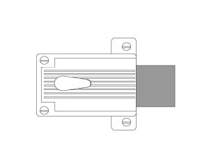
The other kind of rim deadlock is a horizontal deadbolt such as the Yale 112 (see below left).

The Yale 112 features a 1-1/2 inch throw deadbolt – ½ inch longer than what is normally available in a tubular deadbolt.

To achieve bump, pick and drill resistance in a rim deadlock, simply add a UL437 UL listed rim cylinder.  Protect the cylinder with a cylinder guard to increase security still further.

The weakest part of the rim deadlock is the strike when it’s installed into a wooden frame.  To help alleviate this weakness, install screws that are long enough to reach the stud behind the door frame.

On a metal frame, a rim lock strike can be very strong when it is installed correctly.

Mortise Deadbolts

There are two kinds of mortise deadlocks:

  • Small Body Mortise Deadbolts
  • Full Size Mortise Deadbolts

Small body mortise deadbolts are usually installed where most auxiliary locks are installed, six inches to a foot above the primary lock, maybe around 60 inches from the bottom of the door frame.  The lock case of a small body mortise lock is variable – that is, it is not standardized.

A small body mortise deadbolt can be a good choice for a wooden door, especially if it is a thicker-than-usual wooden door.  Since the lock is a good size metal box that gets tucked into an approximately 5 inch by 1/2 inch pocket carved into the wood, the lock utilizes the strength of the door to its best advantage.

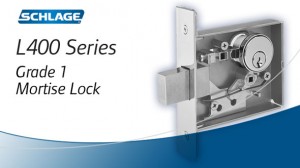
Full size mortise deadbolts are installed in an “86 prep” (see illustration), which is a pocket located on a center line about 40 inches above the bottom of the door frame.  Unlike most other deadbolts, full size mortise deadbolts are intended for use as the primary – and usually the only – lock on any given door.  Full size mortise deadbolts are usually used on mechanical compartments, closets in corridors or other places where trim would be in the way.

Both small body and full size mortise deadbolts feature heavy duty mechanisms and strong, 1-inch projection bolts.  With the addition of a high security, UL437 UL listed mortise cylinder to add bump, pick and drill resistance, mortise deadbolts can provide a high degree of security.


Schlage L460 Series Small Body Mortise Lock


Avoiding Tailpiece Loss Syndrome

SFIC Tailpieces, A.K.A. Throw Members

Tailpiece Loss Syndrome is such a common occurrence in the door hardware industry that it is almost a joke.  It happens like this:

  1. The job specifies small format interchangeable core (SFIC) cylindrical locks
  2. The locks are shipped with separate tailpieces, often called ‘throw members’
  3. The installer (usually a contractor) installs the locks and throws the tailpieces away

This occurs so often that when I get a call from a customer who says, “I have a job where we installed all SFIC cylindrical locks…”  I finish the sentence for them, “… and the contractor threw the tailpieces away.”   That usually gets a chuckle, but there’s not much humor in it really, especially if the tails must be factory ordered with a lead time of several weeks and the inspection is tomorrow.

Nope, no fun.

To avoid losing the tailpieces this way, there are a couple of things you might do:

  • Get a responsible person (maybe you) to collect the tailpieces when the locks are delivered, or
  • Have the tailpieces shipped separately directly to you, or
  • Order cores with the locks and have the contractor install them and ensure they are working properly.  (They will need to have the tails to accomplish this.)

If you elect to order the cores with the locks and want to avoid the delays associated with waiting for an order of master keyed permanent cores, order construction cores.   Construction cores are temporary cores that are all keyed alike for use during the construction phase.  Typically hardware re-sellers stock construction cores or they are readily available from the factory, so they are usually deliverable fairly quickly.


Understanding Door Security Monitor Switches

A number of different kinds of switches are available to help you keep track of whether or not your door is shut and / or locked.  Here are some of them:

Door Status Monitor Switch

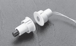
A door status monitor switch changes states when the door is opened or closed.  Typically this is accomplished by using a magnetic reed switch, either surface mounted or concealed in the edge of the door and door frame like the one shown at right.

How a Magnetic Reed Switch Works

The magnetic reed switch is typically installed on the door frame and the magnet that activates the switch is typically installed on the door.   Inside the magnetic reed switch, a thin piece of steel – a steel ‘reed’, if you will – is held in position by the attraction of the magnet when the door is closed.  When the door is opened, the magnet is taken away from the switch and the spring tension of the “reed” causes it to spring back against the other contact, changing the state of the switch.

Most magnetic reed switches are normally closed – “closed loop” – but are also available normally open (“open loop”) SPDT (single pole double throw, or “form C”) or DPDT (double pole double throw).

The Purpose of the Door Status Monitor Switch

The door status monitor switch is used to notify remote devices that a door is open or closed.  Typically these remote devices are burglar alarm panels or access control system controllers.   It does not tell you if the door is locked, just if it is closed.

Request to Exit Switch

The request to exit switch, also known as a REX switch, is so named because it is usually connected to the request to exit contacts on an alarm panel or access control board.  It is used to notify an external device that someone is exiting through, or wants to exit through, a door.  REX switches come in a wide variety of configurations, from push button palm switches engraved “push to exit” to switches concealed inside exit devices.  A motion exit sensor is also a form of request to exit switch.

Request to exit switches are available with a wide variety of contact configurations and with or without electronic or pneumatic time delay.   If the switch is being used as a means of egress for pedestrian traffic, it will need to comply with life safety code.  Life safety code varies from locality to locality as governed by your local AHJ – Authority Having Jurisdiction – that is, your local building inspector or fire marshal.

Latch Bolt Monitor Switch / Strike Monitor Switch

I write about Latch Bolt Monitor (LBM) switches and Strike Monitor Switches because they somewhat overlap.  Both are designed to monitor the position of the latch bolt.

Some LBM switches are inside locks and others are in electric strikes.  From inside the lock, they monitor whether the latch is extended or depressed.  When located in an electric strike, they monitor whether or not there is a latch bolt present in the keeper.

Pictured at right is Securitron’s line of inexpensive strike monitor switches as examples of strike monitor switches.  Several companies offer like products.  Strike monitor switches are an easy way to monitor if there is a latchbolt (or some other object) present in the keeper.   Several companies, such as Von Duprin, offer heavier duty monitor strikes.  Monitor strikes are sold as a finished unit that includes as strike and a switch whereas strike monitor switches are aftermarket add-on units.

Magnetic Bond Sensor / Bond Sensor

Magnetic bond sensor and bond sensor options refer to electromagnetic lock applications.  Many manufacturers offer Bond Sensor or Magnetic Bond Sensor as an option.  What this does is allow an electromagnetic lock to notify some external device that its holding force is below spec.  Authorities are alerted and the situation is addressed.

Maximizing Effectiveness

To maximize effectiveness of door monitor switches, it is best to use both a door status monitor and some kind of lock status monitor as well, and this is why:  because monitor switches can be fooled.  A door status switch will tell you if the door is open or closed – unless it has been altered to tell you the door is closed when it is not.  Also, a door may be closed, but not locked.  If you have a latch bolt monitor or magnetic bond sensor in place as well as a door status switch, you will know if the door is closed but not locked.

This is the center of this knowledge:  to know that the door is shut AND locked.


How to Choose a Door Closer

To intelligently choose a door closer for your application you have to know certain facts:

  • Does the closer need to comply with ADA opening force guidelines?
  • Is the door an interior or exterior door?
  • What is the door width?
  • Will the closer be mounted on the push or pull side of the door?
  • Where on the door will the door closer be installed?  How much room is there?
  • Are there any special circumstances like wind, positive or negative pressure, etc.?
  • You may also need to know the door handing.

ADA Reduced Opening Force Guidelines

American Disabilities Act (ADA) reduced opening force restrictions are enforced by the Authority Having Jurisdiction in your locality.  In some localities or applications ADA requires a maximum opening force of 5 lbs. and in others a maximum opening force of 8.5 lbs.  Most closers on the market today can be field adjusted to comply with these restrictions, but to do so you need to have a door pressure gauge.

I am mildly acquainted with two door pressure gauges.  One is the model DPG by HMC and the other is the ADA/FG by LCN.  Apparently there are a lot of initials involved in door pressure.

Door closers are also available with reduced opening force meant specifically to comply to ADA standards.

Manufacturers usually print a disclaimer that says that a door closer adjusted to ADA maximum opening force may not have enough power to shut the door.  This is often true because perhaps recommended spring strengths for different applications are the result of perhaps a century of innovation.  Manufacturers know that a force greater than 8.5 pounds may be necessary to close a door.

Interior versus Exterior

When speaking about door closer closing force, we say that a door closer is of a certain size.  Door closer size does not refer to actual dimensions, but to spring strength.  Historically, door closers are available in sizes 1 through 6 – 1 being the wimpiest and 6 capable of exerting the strongest closing force.

A size 4 closer is usually recommended for an exterior, 3-foot wide door, whereas a size 3 closer is deemed appropriate for an interior door of the same dimensions.  The assumption here is that the exterior door is more likely to be expected to close a door against a wind or negative or positive air pressure.

Door Width

If you look at a door hung on butt hinges and equipped with a door closer from above, it looks something like this:

View from the Ceiling


You see from the illustration that the door closer closes the door by exerting force on a point about eight or ten inches from the hinge side of the door.  To see what this means, go to a door with no door closer.  Open it.  Now put your hand a foot from the hinge side of the door and push it closed.  Pretty difficult, isn’t it?   If your door was wider, it would be even harder to close from that point.  This is why door closer size – that is, spring strength – is determined by the width of the door rather than the height.

For a three foot wide exterior door, you would normally adjust your door closer to be a size four.  For a four foot wide exterior door you would adjust your door closer to be a size five.  Therefore, if you have a four foot wide exterior door, you had better buy a closer that can be adjusted to a size five.

Push or Pull?

Different arms are required for different applications.  On doors that swing out, where the closer is mounted on the push side, the closer is mounted in a top jamb or parallel arm configuration.  If it is mounted on the pull side it is mounted in what is called a ‘standard’ installation.  (There are other ways to mount a closer on the push side, but parallel arm and top jamb are the most common.)

See manufacturer’s literature for more information, or check out my article on Door Closer Basics.

Room

If you have a glass and aluminum storefront kind of door, you may have a space issue as regards your choice of door closer.  If you have a hollow metal door with no window hung in a steel frame, chances are you will have no space issue.

You need to figure out what door closer will fit.  To do that, measure the space where you would like to install it and download installation templates or instructions from manufacturer’s web sites.  Check the dimensions to see if the closer you have selected will work or not.

Or you can measure your door and frame and consult a door hardware professional.

Special Circumstances

I have installed door closers in some fairly challenging environments.  One, for example, was on a four foot wide, eight foot high, two and a quarter inch thick mahogany and glass door.  In addition to the size of the door, the location was also challenging – right across Beacon Street from the Boston Common where the wind could race across the open ground and dash itself against the door to its heart’s content.  Also, the front of the building had settled over the century or so of its existence, and leaned decidedly inward.  The door opened inward, and, left on its own, would swing sedately inward to 90 degrees if not latched.

In other words I had to install a door closer that would close an extra heavy door, uphill, in a wind.  I actually got one that would do it about 95% of the time.  For this application I chose the most durable, powerful, adjustable door closer I knew at the time:  the LCN 4041.  If I did the same job today I would probably choose an LCN 4011 or a Norton 7500.

A big, beefy, versatile door closer is not a cure-all.  For example, sometimes the 4041 is just too big, or templated too close to the hinge.  The point is that you must look at all the details of your door before you buy a door closer – not only how it is made and its size, but its environment as well.


Exit Devices with Electric Latch Retraction

Overview

Almost all exit device manufacturers offer the option of electric latch retraction on their touch-bar style exit devices.  Different manufactures may call it by other names such as ‘latch pull-back’ or ‘remote dogging’.  Some people refer a device with electric latch retraction as an ‘electrified exit device’, but that could also refer to electric unlocking of outside trim – a different animal altogether.  Electric latch retraction is accomplished by using a solenoid or electric motor to actually retract the latch or latches of an exit device.

Below are some characteristics of electric latch retraction:

  • Electric latch retraction is fail secure.  When power is supplied, the latches retract.  When power is shut off, the latches extend, securing the door.
  • Electric latch retraction works well with power operators because when the latches are retracted, the doors can swing free.
  • With electric latch retraction, pairs of doors can continue to be latched top and bottom.

Cheaper alternatives, such as using an electromagnetic lock or an electric strike, would result in double doors that are only locked at the top.  If they happen to be aluminum narrow stile doors locked only at the top, a person could actually pull the bottom of the locked door open several inches with very little effort.  Such installations are at best sloppy, at worst not secure.  

Solenoid vs. Motorized Latch Retraction

Solenoid driven electric latch retraction usually requires a specialized power supply due to the high inrush of current required (between 12 Amps and 16 Amps at 12 or 24 Volts DC).  Motorized latch retraction generally requires just over 1 Amp of current for activation.  

Solenoids are generally louder than motors, since solenoids move abruptly whereas motors retract at a slightly slower pace, and are therefore quieter.  

Global Considerations

  • Check door width. Electric latch retraction devices may not fit if the door is too narrow.
  • A means of getting current from the door frame into the device, such as a door cord or electric power transfer will be needed.
  • Voltage drop due to length of wire run could be an issue with high current inrush devices.

Following are examples of electric latch retraction exit devices by different manufacturers. 

Please keep in mind that any of the part numbers shown may change without notice at any time.  

Adams Rite

Adams Rite makes hardware primarily for aluminum-and-glass storefront type doors, but also for standard hollow metal and wood doors. All of their exit devices are available with MLR (motorized latch retraction) or solenoid latch retraction (EL for rim devices and LR for all other devices).  They make rim, concealed vertical rod, surface vertical rod, and mortise exit devices.

  • MLR motorized option draws 850 mA during retraction and 370 mA when maintained in dogged hold position at 24 VDC.  Available in 24 VDC only.  (ex. part number 8xxxMLR) 
  • EL solenoid driven option (for rim devices, example part number 8801EL-36-12) draws 1.5 Amps at 12 VDC and 600 mA at 24 VDC
  • LR solenoid driven option (example part number 8xxxLR-36) draws 16 Amps at 24 VDC (inrush) and 500 mA (holding current) at 24 VDC 

They do not offer a retrofit kit for field conversion of existing devices as of this writing, but aftermarket kits are available from other manufacturers.   

Falcon / Doromatic

Falcon makes Doromatic exit devices primarily for aluminum storefront doors. All of their touch-bar style devices are available with electric latch retraction. Currently they use the Von Duprin-type solenoid for latch retraction, and use the Von Duprin PS914-2RS power supply to handle the 16-amp inrush current these solenoids draw.

The PS914-2RS  will power up to 2 exit devices with electric latch retraction.

Doromatic offers a solenoid driven electric latch retraction field retrofit kit for their 1490 series concealed vertical rod and 1590 series rim devices as well as factory installed electric latch retraction. The EL1690 concealed vertical rod device and EL1790 rim device can be used field retrofit kits to electrify the 1990 and 2090 series crossbar “pipe-type” exit devices for latch retraction since they have the same latch side footprint and the vertical rod devices can use the existing rods.  

Falcon offers their grade 1 series 24 and 25 exit devices with electric latch retraction or motorized latch retraction and field conversion kits. 

Falcon exit device example part numbers: 

  • EL solenoid latch retraction (EL25-R-EO 3 US32D)
  • MEL motorized latch retraction (MEL25-R-EO 3 US32D) 

Example field conversion kits: 

  • ELK-3 or ELK-4 (or 650147 or 650148) solenoid latch retraction kit for 3- or 4-foot 24 or 25 series exit devices.  Specify finish. 
  • 25-MELK-3 or 25-MELK-4 (or 47266630 or 47266631) motorized latch retraction kit for 3- or 4-foot 25 series devices only.  24 series MEL devices are factory only.  Specify finish.  

Precision

Precision makes exit devices for hollow metal, aluminum storefront, and wood doors, fire rated and non fire rated. All of their touch bar-style exit devices are available with electric latch retraction, and they offer both solenoid driven and motorized electric latch retraction for their grade 1 devices.   

  • ELR solenoid latch retraction (ex. part number ELR2103 630 36)
  • MLR motorized latch retraction (ex. part number MLR2103 630 36) 

Precision makes retrofit solenoid electric latch retraction kits specific to various device characteristics.   

  • Non-fire rated 3- or 4-foot wide stile exit device:  ELRK-3 / ELRK-4 
  • Fire rated 3- or 4- foot wide stile exit device:  ELRKF-3 / ELRKF-4 
  • Non-fire rated 3- or 4- foot narrow stile exit device:  NELRK-3 / NELRK-4 
  • Fire rated 3- or 4-foot narrow stile exit device:  NELRKF-3 / NELRKF-4 

They make one kit to convert any of their touch bar devices to motorized latch retraction: 

  • RPMLR-K  

Sargent

Sargent offers a wide variety of exit devices in various functions and configurations to accommodate diverse applications. All 80-series models are available with “Remote Dogging / Latch Retraction”.  Sargent recommends the Securitron BPS-24-1 power supply, a simple 1-amp, 24VDC power supply, to power electric latch retraction devices.  

To designate Remote Dogging / Latch Retraction they use a prefix 56- to the exit device part number.

Example part number: 56-8810F 32D 

Sargent offers two kinds of retrofit kits to convert existing Sargent exit devices to motorized latch retraction in the field.  The R56A kit includes a complete touch bar (specify finish) whereas the M56A consists of a motor and control module unit that is unfinished.  Rail size (according to door width) must be specified for either.  Sargent uses letter designations for rail size: 

  • E = 24 to 32 inch door width 
  • F = 33 to 36 inch door width 
  • J = 37 to 42 inch door width 
  • G = 43 to 48 inch door width 

Example part numbers: 

  • Modular kit:  M56AF
  • Push Rail Assembly Kit:  R56AF 32D 

Von Duprin

Von Duprin offers two kinds of electric latch retraction in rim, surface vertical rod, concealed vertical rod, mortise, and three-point exit devices for narrow stile aluminum storefront, standard hollow metal, and wood door applications.  To order exit devices with latch retraction use prefix EL for solenoid latch retraction or QEL for motorized latch retraction.  

EL prefix devices require the PS914-2RS power supply.   PS902-2RS are the manufacturer’s recommendations for QEL prefix devices, but any regulated and filtered power supply 2 Amps or greater will do.  If powering 2 devices simultaneously, the PS902-2RS will stagger the inrush, firing one QEL at a time.  Since each draws 1 Amp, simultaneous activation of two devices might max out a standard 2 Amp power supply.  If another manufacturer’s power supply will be used to power two devices, I suggest using a 3 Amp power supply. 

Wire run/current drop factors apply.  

Example part numbers:  

  • Solenoid latch retraction:  EL99EO 3 26D 
  • Motorized latch retraction:  QEL99EO 3 26D 

Von Duprin offers a variety of retrofit kits to field convert existing exit devices to electric latch retraction.  Options include motorized latch retraction kits, kits that include rail backplate (specify door 3 or 4 foot door width), kits with motorized latch retraction and hex key dogging, etc.   Here I list part numbers for the most common variations:  

  • Solenoid Latch retraction (EL) kits:  
    • For 3-foot door width:  050070 
    • For 4-foot door width:  050078 
  • Motorized latch retraction (QEL) kits: 
    • For 3-foot door width: 958003 
    • For 4-foot door width:  040065 

Dorma

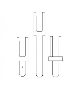
Dorma offers solenoid and motorized latch retraction for their 9000 series exit devices.   ES is the designation for solenoid driven latch retraction and MLR for motorized latch retraction.  They offer full replacement touch bar and rail assemblies that can be used to field convert devices to ES or MLR.   

Example exit device with latch retraction part numbers: 

  • With solenoid latch retraction:  9x00B RHR 630 ES 
  • With motorized latch retraction:  9×00 RHR 630 MLR 

ES option requires Dorma PS501 power supply.  

MLR option, Dorma DKPS-2A power supply recommended, but any 2 Amp regulated and filtered power supply will work.  

Rail size designations:  

  • A – for door width 34 inches to 48 inches
  • B – for door width 28 inches to 36 inches 
  • C – for door width 25 inches to 30 inches 

Touch bar and rail assemblies, example part numbers: 

  • MLR option motorized latch retraction:  MLRTBR 630 B
  • MLR option fire rated motorized latch retraction:  MLRFTBR 630 B
  • ES option solenoid latch retraction:  ESTBR 630 B
  • ES option fire rated solenoid latch retraction:  ESFTBR 630 B 
Easy Hinge Replacement

The easy way to replace worn hinges is to leave the door on its hinges while you replace them.

To do this:

  • You must replace the existing hinges with hinges of the same size
  • On a hollow metal door your hinges must match the hinge prep screw pattern
  • You must be able to open the door far enough so that you can reach the screws on the door leaf of the hinge with your screwdriver – typically you would need to open the door to about 100 degrees of opening

If any of these is not the case, stop right here and go get some help.   You will need to take down the door, put it in a door stand and replace the hinges one leaf at a time, the old fashioned way.

You will need:

  • A screwdriver that fits your hinge screws, most likely a number 3 Phillips head
  • A ladder
  • A piece of 1 x 4 pine between 2 and 3 feet long or similar piece of wood
  • Wood shim stock

If you are replacing hinges with the same size hinges and can open the door wide enough, go ahead and open the door to the degree of opening that best allows you to access all the hinges screws on both leaves.  Beneath the door place the piece of pine, and then between the pine and the bottom of the door stack shim stock until the door is fully supported by the wood.  If there is a closer on the door, the door should be resting securely enough on the wood shims so that the closer cannot close the door.  However, the door should be shimmed just enough to take the tension off the hinges – no more.  You want the hinge preps to remain as properly aligned as possible.

Once you have shimmed the door you can replace the hinges.   Start with the top.  Install each leaf with two screws only, not quite fully tightened.  Then move on to the next hinge, then the next, until they are all replaced.   When each hinge is in place with two screws in each leaf, tighten all the screws and try the door.  If the hinges bind or make noise, something is amiss and needs further adjustment.

If applicable, put masking tape over the strike plate and close the door.  Is the door happy to remain closed, or does it want to spring open?  If it wants to spring open, chances are the new hinges aren’t quite as thick as the old hinges and need to be shimmed.  Support the door with wood as before and inspect the hinges.  Both leaves should be flush.  If they appear to be inset, shim them out with very thin slices of wood that are the same height as the hinge prep.  Continue as necessary until when tested the door is stable when fully closed.

Troubleshooting

If the hinges bind or make noise, remove the screws from one leaf of the middle hinge and gently pry it out of the hinge prep.  Test the door again.  If the door still binds or makes noise, put the screws back in the middle hinge and try removing the screws from one leaf of the bottom hinge.   By this method you should be able to isolate the hinges that are binding and then look closer to determine the exact problem.

If, as you are working, you find that the hinge preps aren’t lining up so well, the door may have settled on the hinges – particularly if they are plain bearing, five knuckle steel butt hinges and they have been there a long time or had heavy use.  You may find that you have to shim the door up just a bit more to get the hinge preps to line up right for the new hinges.

If there is no possible way to get the hinge preps to line up right then you may be dealing with a deeper issue than simple hinge replacement.  Your best choice might be to put the old hinges back and then decide whether you want to replace the door, frame, or both, or whether you can use a surface mount continuous hinge instead.

Click here to read more about hinges.


Tags