You have searched the Door Hardware Genius blog archives for 4. If you are unable to find anything in these search results, you can try with different search query


Understanding Door Security Monitor Switches

A number of different kinds of switches are available to help you keep track of whether or not your door is shut and / or locked.  Here are some of them:

Door Status Monitor Switch

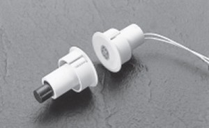
A door status monitor switch changes states when the door is opened or closed.  Typically this is accomplished by using a magnetic reed switch, either surface mounted or concealed in the edge of the door and door frame like the one shown at right.

How a Magnetic Reed Switch Works

The magnetic reed switch is typically installed on the door frame and the magnet that activates the switch is typically installed on the door.   Inside the magnetic reed switch, a thin piece of steel – a steel ‘reed’, if you will – is held in position by the attraction of the magnet when the door is closed.  When the door is opened, the magnet is taken away from the switch and the spring tension of the “reed” causes it to spring back against the other contact, changing the state of the switch.

Most magnetic reed switches are normally closed – “closed loop” – but are also available normally open (“open loop”) SPDT (single pole double throw, or “form C”) or DPDT (double pole double throw).

The Purpose of the Door Status Monitor Switch

The door status monitor switch is used to notify remote devices that a door is open or closed.  Typically these remote devices are burglar alarm panels or access control system controllers.   It does not tell you if the door is locked, just if it is closed.

Request to Exit Switch

The request to exit switch, also known as a REX switch, is so named because it is usually connected to the request to exit contacts on an alarm panel or access control board.  It is used to notify an external device that someone is exiting through, or wants to exit through, a door.  REX switches come in a wide variety of configurations, from push button palm switches engraved “push to exit” to switches concealed inside exit devices.  A motion exit sensor is also a form of request to exit switch.

Request to exit switches are available with a wide variety of contact configurations and with or without electronic or pneumatic time delay.   If the switch is being used as a means of egress for pedestrian traffic, it will need to comply with life safety code.  Life safety code varies from locality to locality as governed by your local AHJ – Authority Having Jurisdiction – that is, your local building inspector or fire marshal.

Latch Bolt Monitor Switch / Strike Monitor Switch

I write about Latch Bolt Monitor (LBM) switches and Strike Monitor Switches because they somewhat overlap.  Both are designed to monitor the position of the latch bolt.

Some LBM switches are inside locks and others are in electric strikes.  From inside the lock, they monitor whether the latch is extended or depressed.  When located in an electric strike, they monitor whether or not there is a latch bolt present in the keeper.

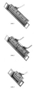
Pictured at right is Securitron’s line of inexpensive strike monitor switches as examples of strike monitor switches.  Several companies offer like products.  Strike monitor switches are an easy way to monitor if there is a latchbolt (or some other object) present in the keeper.   Several companies, such as Von Duprin, offer heavier duty monitor strikes.  Monitor strikes are sold as a finished unit that includes as strike and a switch whereas strike monitor switches are aftermarket add-on units.

Magnetic Bond Sensor / Bond Sensor

Magnetic bond sensor and bond sensor options refer to electromagnetic lock applications.  Many manufacturers offer Bond Sensor or Magnetic Bond Sensor as an option.  What this does is allow an electromagnetic lock to notify some external device that its holding force is below spec.  Authorities are alerted and the situation is addressed.

Maximizing Effectiveness

To maximize effectiveness of door monitor switches, it is best to use both a door status monitor and some kind of lock status monitor as well, and this is why:  because monitor switches can be fooled.  A door status switch will tell you if the door is open or closed – unless it has been altered to tell you the door is closed when it is not.  Also, a door may be closed, but not locked.  If you have a latch bolt monitor or magnetic bond sensor in place as well as a door status switch, you will know if the door is closed but not locked.

This is the center of this knowledge:  to know that the door is shut AND locked.


How to Choose a Door Closer

To intelligently choose a door closer for your application you have to know certain facts:

  • Does the closer need to comply with ADA opening force guidelines?
  • Is the door an interior or exterior door?
  • What is the door width?
  • Will the closer be mounted on the push or pull side of the door?
  • Where on the door will the door closer be installed?  How much room is there?
  • Are there any special circumstances like wind, positive or negative pressure, etc.?
  • You may also need to know the door handing.

ADA Reduced Opening Force Guidelines

American Disabilities Act (ADA) reduced opening force restrictions are enforced by the Authority Having Jurisdiction in your locality.  In some localities or applications ADA requires a maximum opening force of 5 lbs. and in others a maximum opening force of 8.5 lbs.  Most closers on the market today can be field adjusted to comply with these restrictions, but to do so you need to have a door pressure gauge.

I am mildly acquainted with two door pressure gauges.  One is the model DPG by HMC and the other is the ADA/FG by LCN.  Apparently there are a lot of initials involved in door pressure.

Door closers are also available with reduced opening force meant specifically to comply to ADA standards.

Manufacturers usually print a disclaimer that says that a door closer adjusted to ADA maximum opening force may not have enough power to shut the door.  This is often true because perhaps recommended spring strengths for different applications are the result of perhaps a century of innovation.  Manufacturers know that a force greater than 8.5 pounds may be necessary to close a door.

Interior versus Exterior

When speaking about door closer closing force, we say that a door closer is of a certain size.  Door closer size does not refer to actual dimensions, but to spring strength.  Historically, door closers are available in sizes 1 through 6 – 1 being the wimpiest and 6 capable of exerting the strongest closing force.

A size 4 closer is usually recommended for an exterior, 3-foot wide door, whereas a size 3 closer is deemed appropriate for an interior door of the same dimensions.  The assumption here is that the exterior door is more likely to be expected to close a door against a wind or negative or positive air pressure.

Door Width

If you look at a door hung on butt hinges and equipped with a door closer from above, it looks something like this:

View from the Ceiling


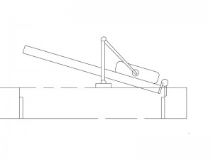
You see from the illustration that the door closer closes the door by exerting force on a point about eight or ten inches from the hinge side of the door.  To see what this means, go to a door with no door closer.  Open it.  Now put your hand a foot from the hinge side of the door and push it closed.  Pretty difficult, isn’t it?   If your door was wider, it would be even harder to close from that point.  This is why door closer size – that is, spring strength – is determined by the width of the door rather than the height.

For a three foot wide exterior door, you would normally adjust your door closer to be a size four.  For a four foot wide exterior door you would adjust your door closer to be a size five.  Therefore, if you have a four foot wide exterior door, you had better buy a closer that can be adjusted to a size five.

Push or Pull?

Different arms are required for different applications.  On doors that swing out, where the closer is mounted on the push side, the closer is mounted in a top jamb or parallel arm configuration.  If it is mounted on the pull side it is mounted in what is called a ‘standard’ installation.  (There are other ways to mount a closer on the push side, but parallel arm and top jamb are the most common.)

See manufacturer’s literature for more information, or check out my article on Door Closer Basics.

Room

If you have a glass and aluminum storefront kind of door, you may have a space issue as regards your choice of door closer.  If you have a hollow metal door with no window hung in a steel frame, chances are you will have no space issue.

You need to figure out what door closer will fit.  To do that, measure the space where you would like to install it and download installation templates or instructions from manufacturer’s web sites.  Check the dimensions to see if the closer you have selected will work or not.

Or you can measure your door and frame and consult a door hardware professional.

Special Circumstances

I have installed door closers in some fairly challenging environments.  One, for example, was on a four foot wide, eight foot high, two and a quarter inch thick mahogany and glass door.  In addition to the size of the door, the location was also challenging – right across Beacon Street from the Boston Common where the wind could race across the open ground and dash itself against the door to its heart’s content.  Also, the front of the building had settled over the century or so of its existence, and leaned decidedly inward.  The door opened inward, and, left on its own, would swing sedately inward to 90 degrees if not latched.

In other words I had to install a door closer that would close an extra heavy door, uphill, in a wind.  I actually got one that would do it about 95% of the time.  For this application I chose the most durable, powerful, adjustable door closer I knew at the time:  the LCN 4041.  If I did the same job today I would probably choose an LCN 4011 or a Norton 7500.

A big, beefy, versatile door closer is not a cure-all.  For example, sometimes the 4041 is just too big, or templated too close to the hinge.  The point is that you must look at all the details of your door before you buy a door closer – not only how it is made and its size, but its environment as well.


What’s Hot in Door Hardware

A couple of new innovative products have recently caught my attention.  Here they are:

Security Door Controls (SDC) Model LR100VDK:

Field Installed Electric Latch Retraction Retrofit Kit for Von Duprin Exit Devices


This product is available now.

http://www.sdcsecurity.com/whatsnew2.aspx#lr100

The mere 450mA inrush powering Security Door Controls’ new electric latch retraction retrofit kit is attractive enough.  Its compatibility with all Von Duprin touch bar style devices may make it just about irresistible.   Optional request to exit switch kits are available.  The unit is usable for access control and electric dogging applications.

The small inrush is huge.  (I always wanted to say that.)  High inrush electric latch retraction requires special, expensive power supplies.  Not so with the LR100VDK.  Your average regulated and filtered 1-amp 24vdc power supply will do nicely, thank you.

Another great aspect of this kit is that it is compatible with the Von Duprin 22 series exit device. So now, for relatively short money you can give a customer electric latch retraction in a decent quality exit device.

HES Model 8500 Electric Strike for Mortise Locks


http://www.hesinnovations.com/en/site/hesinnovations/Products-startpage/?groupId=141798&productId=764670

This product is due to become available by the end of August, 2011, but we’ll see.

Hanchett Entry Systems’ new lipless electric strike solution for mortise locks.

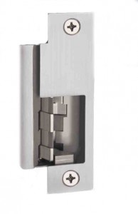
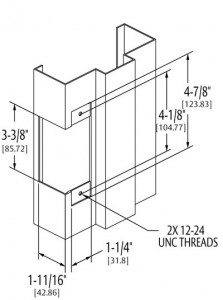
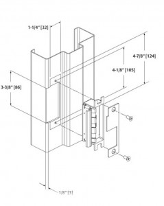
Installing an electric strike to release a mortise lock will be much easier with the HES 8500 since no cutting of the face of the frame is necessary.  Below is an illustration showing the difference between the HES 1006 standard electric strike for mortise lock and the new HES 8500.

HES 1006 prep for hollow metal

HES 8500 door prep for hollow metal - look ma, no lip!


This is not a new idea, but installers seem excited about the prospect of having an alternative to the Securitron UnLatch, which has been around for quite some time.  The Unlatch model that the HES 8500 will compete with will be the Securitron MUNL.

Of course, the advantage the MUNL currently enjoys is that, unlike the 8500, one can actually buy an MUNL.  Comparatively, the Securitron requires a door frame depth of about 1-7/8 inches whereas the the 8500 will require about 1-3/8 inches.  The 8500 will draw 240mA at 12 volts DC and 120mA at 24 volts DC and draws no inrush current.  The MUNL has an inrush of 2 amps at 24vdc or 4 amps at 12vdc and an operating current of 600mA at 12vdc or 300mA at 24vdc.  One important result of the lower current consumption of the 8500 will be that instead of the 4 amp 12vdc or 8 amp 24vdc power supply necessary for each MUNL, one 8 amp 24vdc power supply will theoretically power as many as perhaps 60 of the new HES 8500.  Of course then, factors like wire run will come into play, but still.

Another positive attribute will be that the 8500 will be field selectable for fail safe or fail secure whereas the MUNL requires an additional module to make it fail safe.

All in all, the 8500 seems that it will be a better choice all around.  We’ll just have to wait and see how it performs in the field after it becomes available at the end of August 2011.

Alphabetical Index

locksnsafescom

Your source for quality security products with superior service!


Low Voltage Detective Work


Finding the Current Drop


As electric locking systems become increasingly complicated, troubleshooting these systems has also become more complex.  Yet certain basic principles always apply.

Case in point, a customer had access control on a stairwell door using a fire rated mortise exit device with an electrified mortise lock.  The solenoid in the mortise lock had burned out twice and the third one, newly installed, was already too hot to touch.  Granted, a solenoid operated fail safe device used in a continuous duty application will get warm, but it should not get too hot to touch.  So they called me to help them figure out what was going on.

To find the problem, I first listed the possibilities:

  1. They had gotten three defective solenoids in a row
  2. The power supplied is the wrong voltage – if the voltage was either too high or low, that would cause the solenoid to heat up
  3. The current supplied is inadequate – the solenoid used 330mA.  If it were being supplied with only 150mA, for example, the solenoid would heat up.

We determined that 27 volts DC was available at the door to power the 24 volts DC solenoid – perfectly acceptable – and we all felt that it was rather unlikely that they had received three defective solenoids in a row.  So that left current drop.  Where was the current going?  What was preventing it from getting the current it needed?

The access control tech on site could not determine whether the solenoid was getting enough current at the door by using a meter (for whatever reason) so we traced the current back through the line.

The power supply was a 6 amp, 24 volts DC power supply that had an output board with 8 fused outputs.  If all were in use, then a max of 750mA should be available from each output, provided they all were carrying the same amperage load.  We determined that four of the outputs were being used:  three were used to power electric strikes at 300mA and one was used to power the electric mortise exit device at 330mA.  The sum of the current draw for all devices attached to the power supply was therefore about 1.2 amps – well within the power supply’s capacity.  Therefore the power supply size was not the problem.  The technician measured the output from the contacts that were connected to the mortise lock and found that they were outputting correct voltage and current.  Therefore the output board was not the problem.

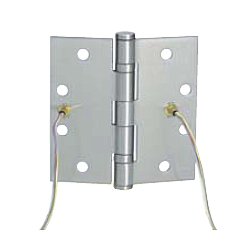
Assured by the technician that the wire run between the power supply and the mortise lock was less than 100 feet and that 18 gauge wire was used, I knew that the wire run was not the problem.  I asked how power got from the door frame through the door and into the mortise lock.  The technician responded that power transfer was accomplished by use on an electric hinge.

Typical wire gauge in an electric hinge is 24 gauge – a thin wire to be sure, but since power only needs travel a few inches through it, hinge wire gauge is usually not a problem.  But this electric hinge had its own 3-foot wire lead threaded through a raceway in the door to the mortise lock.  Whereas a few inches of 24 gauge wire might not be a problem, I reasoned, three feet of it might be a problem.  We talked about it briefly and then agreed that they would give it a try.

To my dismay, they called back two hours later – after they had replaced the wire running through the door with 18 gauge wire and let the mortise lock run on it for a while – and let me know that this did not work either.

The answer finally came when I asked how the electric mortise lock was connected to access control and was told there was a controller in a box above the door.  The controller used a form C relay to turn the electric mortise lock on and off.  I suggested that the technicians check the relay to make sure it was working properly.  When they did they discovered that the electric mortise lock had been connected in series with another device.  This other device – whatever it was – drew enough current to deprive the mortise lock of the current it needed to operate without burning up.  Problem solved.

The moral of the story is that, yes, access control has only gotten more complex as time goes by, but by using simple, logical methods a good technician and figure out and repair most problems.  So stick with it and keep asking questions until you ask the right one.


And good luck!


Door Propped Alarm

Overview

The purpose of a Door Propped Alarm is to sound an alarm when a door has been left open after a pre-determined period of time – a function that is deceptively complex.   The motivation for this function is usually that a door is left unlocked or open when it should be closed and/or locked.  Many access control systems include Door Propped Alarm capabilities, but stand-alone Door Propped Alarms are also available.

First, to clear up a common misconception, a Door Propped Alarm is not an exit alarm.

An exit alarm is a relatively simple device that screams when a door is opened.  Usually it is equipped with an audible local alarm, a cylinder, keypad or credential reader for reset and authorized bypass, and a door position switch to tell the alarm when to scream.  In recent years the exit alarm has grown more sophisticated, incorporating timers for automatic reset, delayed arming and other complex functions.

A Door Propped Alarm must accomplish a more complex set of operations because of the variety of user needs and expectations.  A lot of this variety stems from vocabulary issues.  For example, many users will refer to a door as being “closed” when they really mean, ‘locked.’  A true Door Propped Alarm will have the flexibility to accommodate these varied expectations.

Function

The condition that creates the need for a Door Propped Alarm is the need to leave the door open for a period of time, but no longer.  For our discussion, we’ll call this period of time the Authorized Open Period.  This is the most important time segment a Door Propped Alarm needs to track.

The next time segment that a user may want the Door Propped alarm to track might be what could be called the Pre-Alarm state.  Typically in this state the Door Propped alarm will change the state of one or more relays.  These relays can be used to notify other equipment to create a warning sound, lock other doors, or for many other functions.  The warning sound is useful because it allows the user to close to door before the Door Propped Alarm goes into full alarm.  In the Pre-Alarm state, the Door Propped Alarm could be set up to automatically reset when the door is closed and/or locked.

The Alarm State may or may not be a timed function, that is, it may have the ability to self-reset after a pre-programmed amount of time that would begin when the door is closed and/or locked, or it may require manual reset at the door by key or other credential.  In the Alarm State, the Door Propped Alarm may have an on-board siren or may change the state of a relay to sound an external alarm.

Necessary Switches

In order to work, a Door Propped Alarm needs a door status switch.  Depending on what the user wants the Door Propped Alarm to do, it also may need a lock status switch.  If the user wants to sometimes leave the door open or unlocked without the alarm going off, some kind of secure access control, such as a key switch, keypad or credential reader, will be necessary to temporarily bypass the Door Propped Alarm.  If the user wants to require that the alarm be silenced and reset at the door for extra security, a key switch or other secure access control will be needed.

To get an even better idea of the functionality of a Door Propped Alarm, go to Securitron’s web site and search out the installation instructions for their DPA-12 or DPA-24 Door Propped Alarm.


Exit Devices with Electric Latch Retraction

Overview

Almost all exit device manufacturers offer the option of electric latch retraction on their touch-bar style exit devices.  Different manufactures may call it by other names such as ‘latch pull-back’ or ‘remote dogging’.  Some people refer a device with electric latch retraction as an ‘electrified exit device’, but that could also refer to electric unlocking of outside trim – a different animal altogether.  Electric latch retraction is accomplished by using a solenoid or electric motor to actually retract the latch or latches of an exit device.

Below are some characteristics of electric latch retraction:

  • Electric latch retraction is fail secure.  When power is supplied, the latches retract.  When power is shut off, the latches extend, securing the door.
  • Electric latch retraction works well with power operators because when the latches are retracted, the doors can swing free.
  • With electric latch retraction, pairs of doors can continue to be latched top and bottom.

Cheaper alternatives, such as using an electromagnetic lock or an electric strike, would result in double doors that are only locked at the top.  If they happen to be aluminum narrow stile doors locked only at the top, a person could actually pull the bottom of the locked door open several inches with very little effort.  Such installations are at best sloppy, at worst not secure.  

Solenoid vs. Motorized Latch Retraction

Solenoid driven electric latch retraction usually requires a specialized power supply due to the high inrush of current required (between 12 Amps and 16 Amps at 12 or 24 Volts DC).  Motorized latch retraction generally requires just over 1 Amp of current for activation.  

Solenoids are generally louder than motors, since solenoids move abruptly whereas motors retract at a slightly slower pace, and are therefore quieter.  

Global Considerations

  • Check door width. Electric latch retraction devices may not fit if the door is too narrow.
  • A means of getting current from the door frame into the device, such as a door cord or electric power transfer will be needed.
  • Voltage drop due to length of wire run could be an issue with high current inrush devices.

Following are examples of electric latch retraction exit devices by different manufacturers. 

Please keep in mind that any of the part numbers shown may change without notice at any time.  

Adams Rite

Adams Rite makes hardware primarily for aluminum-and-glass storefront type doors, but also for standard hollow metal and wood doors. All of their exit devices are available with MLR (motorized latch retraction) or solenoid latch retraction (EL for rim devices and LR for all other devices).  They make rim, concealed vertical rod, surface vertical rod, and mortise exit devices.

  • MLR motorized option draws 850 mA during retraction and 370 mA when maintained in dogged hold position at 24 VDC.  Available in 24 VDC only.  (ex. part number 8xxxMLR) 
  • EL solenoid driven option (for rim devices, example part number 8801EL-36-12) draws 1.5 Amps at 12 VDC and 600 mA at 24 VDC
  • LR solenoid driven option (example part number 8xxxLR-36) draws 16 Amps at 24 VDC (inrush) and 500 mA (holding current) at 24 VDC 

They do not offer a retrofit kit for field conversion of existing devices as of this writing, but aftermarket kits are available from other manufacturers.   

Falcon / Doromatic

Falcon makes Doromatic exit devices primarily for aluminum storefront doors. All of their touch-bar style devices are available with electric latch retraction. Currently they use the Von Duprin-type solenoid for latch retraction, and use the Von Duprin PS914-2RS power supply to handle the 16-amp inrush current these solenoids draw.

The PS914-2RS  will power up to 2 exit devices with electric latch retraction.

Doromatic offers a solenoid driven electric latch retraction field retrofit kit for their 1490 series concealed vertical rod and 1590 series rim devices as well as factory installed electric latch retraction. The EL1690 concealed vertical rod device and EL1790 rim device can be used field retrofit kits to electrify the 1990 and 2090 series crossbar “pipe-type” exit devices for latch retraction since they have the same latch side footprint and the vertical rod devices can use the existing rods.  

Falcon offers their grade 1 series 24 and 25 exit devices with electric latch retraction or motorized latch retraction and field conversion kits. 

Falcon exit device example part numbers: 

  • EL solenoid latch retraction (EL25-R-EO 3 US32D)
  • MEL motorized latch retraction (MEL25-R-EO 3 US32D) 

Example field conversion kits: 

  • ELK-3 or ELK-4 (or 650147 or 650148) solenoid latch retraction kit for 3- or 4-foot 24 or 25 series exit devices.  Specify finish. 
  • 25-MELK-3 or 25-MELK-4 (or 47266630 or 47266631) motorized latch retraction kit for 3- or 4-foot 25 series devices only.  24 series MEL devices are factory only.  Specify finish.  

Precision

Precision makes exit devices for hollow metal, aluminum storefront, and wood doors, fire rated and non fire rated. All of their touch bar-style exit devices are available with electric latch retraction, and they offer both solenoid driven and motorized electric latch retraction for their grade 1 devices.   

  • ELR solenoid latch retraction (ex. part number ELR2103 630 36)
  • MLR motorized latch retraction (ex. part number MLR2103 630 36) 

Precision makes retrofit solenoid electric latch retraction kits specific to various device characteristics.   

  • Non-fire rated 3- or 4-foot wide stile exit device:  ELRK-3 / ELRK-4 
  • Fire rated 3- or 4- foot wide stile exit device:  ELRKF-3 / ELRKF-4 
  • Non-fire rated 3- or 4- foot narrow stile exit device:  NELRK-3 / NELRK-4 
  • Fire rated 3- or 4-foot narrow stile exit device:  NELRKF-3 / NELRKF-4 

They make one kit to convert any of their touch bar devices to motorized latch retraction: 

  • RPMLR-K  

Sargent

Sargent offers a wide variety of exit devices in various functions and configurations to accommodate diverse applications. All 80-series models are available with “Remote Dogging / Latch Retraction”.  Sargent recommends the Securitron BPS-24-1 power supply, a simple 1-amp, 24VDC power supply, to power electric latch retraction devices.  

To designate Remote Dogging / Latch Retraction they use a prefix 56- to the exit device part number.

Example part number: 56-8810F 32D 

Sargent offers two kinds of retrofit kits to convert existing Sargent exit devices to motorized latch retraction in the field.  The R56A kit includes a complete touch bar (specify finish) whereas the M56A consists of a motor and control module unit that is unfinished.  Rail size (according to door width) must be specified for either.  Sargent uses letter designations for rail size: 

  • E = 24 to 32 inch door width 
  • F = 33 to 36 inch door width 
  • J = 37 to 42 inch door width 
  • G = 43 to 48 inch door width 

Example part numbers: 

  • Modular kit:  M56AF
  • Push Rail Assembly Kit:  R56AF 32D 

Von Duprin

Von Duprin offers two kinds of electric latch retraction in rim, surface vertical rod, concealed vertical rod, mortise, and three-point exit devices for narrow stile aluminum storefront, standard hollow metal, and wood door applications.  To order exit devices with latch retraction use prefix EL for solenoid latch retraction or QEL for motorized latch retraction.  

EL prefix devices require the PS914-2RS power supply.   PS902-2RS are the manufacturer’s recommendations for QEL prefix devices, but any regulated and filtered power supply 2 Amps or greater will do.  If powering 2 devices simultaneously, the PS902-2RS will stagger the inrush, firing one QEL at a time.  Since each draws 1 Amp, simultaneous activation of two devices might max out a standard 2 Amp power supply.  If another manufacturer’s power supply will be used to power two devices, I suggest using a 3 Amp power supply. 

Wire run/current drop factors apply.  

Example part numbers:  

  • Solenoid latch retraction:  EL99EO 3 26D 
  • Motorized latch retraction:  QEL99EO 3 26D 

Von Duprin offers a variety of retrofit kits to field convert existing exit devices to electric latch retraction.  Options include motorized latch retraction kits, kits that include rail backplate (specify door 3 or 4 foot door width), kits with motorized latch retraction and hex key dogging, etc.   Here I list part numbers for the most common variations:  

  • Solenoid Latch retraction (EL) kits:  
    • For 3-foot door width:  050070 
    • For 4-foot door width:  050078 
  • Motorized latch retraction (QEL) kits: 
    • For 3-foot door width: 958003 
    • For 4-foot door width:  040065 

Dorma

Dorma offers solenoid and motorized latch retraction for their 9000 series exit devices.   ES is the designation for solenoid driven latch retraction and MLR for motorized latch retraction.  They offer full replacement touch bar and rail assemblies that can be used to field convert devices to ES or MLR.   

Example exit device with latch retraction part numbers: 

  • With solenoid latch retraction:  9x00B RHR 630 ES 
  • With motorized latch retraction:  9×00 RHR 630 MLR 

ES option requires Dorma PS501 power supply.  

MLR option, Dorma DKPS-2A power supply recommended, but any 2 Amp regulated and filtered power supply will work.  

Rail size designations:  

  • A – for door width 34 inches to 48 inches
  • B – for door width 28 inches to 36 inches 
  • C – for door width 25 inches to 30 inches 

Touch bar and rail assemblies, example part numbers: 

  • MLR option motorized latch retraction:  MLRTBR 630 B
  • MLR option fire rated motorized latch retraction:  MLRFTBR 630 B
  • ES option solenoid latch retraction:  ESTBR 630 B
  • ES option fire rated solenoid latch retraction:  ESFTBR 630 B 
Easy Hinge Replacement

The easy way to replace worn hinges is to leave the door on its hinges while you replace them.

To do this:

  • You must replace the existing hinges with hinges of the same size
  • On a hollow metal door your hinges must match the hinge prep screw pattern
  • You must be able to open the door far enough so that you can reach the screws on the door leaf of the hinge with your screwdriver – typically you would need to open the door to about 100 degrees of opening

If any of these is not the case, stop right here and go get some help.   You will need to take down the door, put it in a door stand and replace the hinges one leaf at a time, the old fashioned way.

You will need:

  • A screwdriver that fits your hinge screws, most likely a number 3 Phillips head
  • A ladder
  • A piece of 1 x 4 pine between 2 and 3 feet long or similar piece of wood
  • Wood shim stock

If you are replacing hinges with the same size hinges and can open the door wide enough, go ahead and open the door to the degree of opening that best allows you to access all the hinges screws on both leaves.  Beneath the door place the piece of pine, and then between the pine and the bottom of the door stack shim stock until the door is fully supported by the wood.  If there is a closer on the door, the door should be resting securely enough on the wood shims so that the closer cannot close the door.  However, the door should be shimmed just enough to take the tension off the hinges – no more.  You want the hinge preps to remain as properly aligned as possible.

Once you have shimmed the door you can replace the hinges.   Start with the top.  Install each leaf with two screws only, not quite fully tightened.  Then move on to the next hinge, then the next, until they are all replaced.   When each hinge is in place with two screws in each leaf, tighten all the screws and try the door.  If the hinges bind or make noise, something is amiss and needs further adjustment.

If applicable, put masking tape over the strike plate and close the door.  Is the door happy to remain closed, or does it want to spring open?  If it wants to spring open, chances are the new hinges aren’t quite as thick as the old hinges and need to be shimmed.  Support the door with wood as before and inspect the hinges.  Both leaves should be flush.  If they appear to be inset, shim them out with very thin slices of wood that are the same height as the hinge prep.  Continue as necessary until when tested the door is stable when fully closed.

Troubleshooting

If the hinges bind or make noise, remove the screws from one leaf of the middle hinge and gently pry it out of the hinge prep.  Test the door again.  If the door still binds or makes noise, put the screws back in the middle hinge and try removing the screws from one leaf of the bottom hinge.   By this method you should be able to isolate the hinges that are binding and then look closer to determine the exact problem.

If, as you are working, you find that the hinge preps aren’t lining up so well, the door may have settled on the hinges – particularly if they are plain bearing, five knuckle steel butt hinges and they have been there a long time or had heavy use.  You may find that you have to shim the door up just a bit more to get the hinge preps to line up right for the new hinges.

If there is no possible way to get the hinge preps to line up right then you may be dealing with a deeper issue than simple hinge replacement.  Your best choice might be to put the old hinges back and then decide whether you want to replace the door, frame, or both, or whether you can use a surface mount continuous hinge instead.

Click here to read more about hinges.


Wiring Through a Door

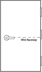
AKA coring the door or drilling a raceway.

Like Moses leading the Hebrews across the Red Sea, you must work a miracle to bring electricity from the hinge side of the door to the lock side.  Luckily it is a miracle on a much smaller scale.  Moses had to deal with millions of gallons of water and miles of sea bottom whereas you only have to deal with a few feet of wood.   So relax.

Raceway Reasons

The best way to get a wire raceway into a door is to order the door with it already built in.  This is especially true of hollow metal doors which often have cross members inside at angles to where the through-wire needs to go.  However, that would require planning in advance – a rare occurrence these days, it seems.    Lack of planning is the main reason that field-drilling a raceway becomes a necessity.

Coring the door is usually the best option whenever you are installing an electric lockset.  This is true whether you use a door cord or an electric hinge.  The safest place for the wire is inside the door.

You will probably also need to drill a raceway if you are using an electric strike in the inactive leaf of a pair of doors.   Usually you will also need a door cord, electric hinge or other power transfer.

Horizontal vs. Vertical

Electric Through-Wire Hinge

It is possible to drill a raceway with the door still up.  I have done it but I don’t recommend it.  It takes nerves of steel and a stiff, sharp drill bit.  You need a decent sized bit that won’t bend right or left on you as you try to drill straight, and you need to make sure that the door doesn’t move on its hinges while you are drilling.

I found that taking the door down and standing it on edge in a homemade door stand is the easiest for me because:

  • The door is much less likely to move while you are drilling it
  • Using a level to guide you is much easier, and
  • Gravity is on your side

Constants

Certain constants apply to either horizontal or vertical drilling.  In both cases I recommend a 3/8-inch by 3-foot drill bit.  If the door is more than 3 feet wide, drill it from both sides or get a 4-foot bit.  I prefer to drill from both sides because it’s a lot easier to drill straight for 18 or 24 inches than it is to drill straight for 3 or 4 feet.

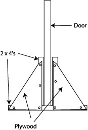
Simple Door Stand

If you have a drill with a built-in level, use it.  If your drill does not have a built-in level, any level will do.  Just put it against the door anytime you want to check the angle at which you are drilling.  Determine if the door has a beveled edge and don’t let the bevel skew your path through the door.  Make sure your drill bit remains parallel to both the interior and exterior surfaces of the door.


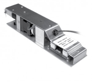
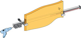
Drilling a raceway across a door is a challenge, but all it really takes is good focus and an ability to drill a straight hole.  If you are challenged in the latter aspect, you might consider a drilling tool like the Security Door Controls product shown below.   If you have many raceways to drill, a tool like this one is a great idea.

Security Door Controls 7000IDF Door Drilling Kit


Exit Device, Panic Hardware and Crash Bar Basics

Introduction

The terms “crash bar”, “panic hardware” and “exit device” all mean the same thing.

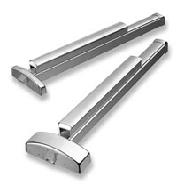
Precision Apex 2000 Series Rim Exit Devices by Stanley

Exit devices are used on doors in the path of egress in buildings built to accomodate numbers of people.  Facilities like schools, hospitals, goverment buildings and large residential buildings all use them.  Fire rated exit devices are used on fire rated doors.  Most interior doors that require exit devices, especially stairwell doors, are fire rated.

Fire Rated Exit Devices

Fire rated openings require fire rated exit devices. Fire rated devices are so designated by Underwriters Laboratories. I am told that UL tests them by mounting the device on a fire rated door and setting the door on fire, letting it burn for a time, and then blasting the door full blast with a fire hose. If the door opens, the device fails the test and cannot be sold as a fire rated exit device.

Non-fire-rated exit devices are used mainly on exterior doors.

Dogging Feature

One of the chief differences between a fire rated exit device and a non-fire-rated exit device is called the “dogging” feature. A dogging feature allows the user to “dog the bar down” using a hex wrench or standard key, leaving the door unlatched. Since fire rated devices must always postitively latch, they never have a dogging feature.

Narrow Stile Exit Devices

The term, “lock stile”, refers to the part of a panel door or aluminum-and-glass storefront door onto which an exit device or other lock is installed. Many aluminum storefront doors one encounters in the world have lock stiles only 1-3/4 inches to 2 inches wide. If you need an exit device for such a door, you need an exit device for a narrow stile application.

Exit Device Types

The four main types of exit devices are:

  • Rim
  • Mortise
  • Surface Vertical Rod
  • Concealed Vertical Rod
  • Mid-panel

See examples of rim exit devices at:

http://www.sargentlock.com/products/product_overview.php?item_id=86

and

http://www.sargentlock.com/products/product_overview.php?item_id=57

See an example of a surface vertical rod device at:

http://www.sargentlock.com/products/product_overview.php?item_id=56

See an example of a mortise exit device at:

http://www.sargentlock.com/products/product_overview.php?item_id=59

See an example of a concealed vertical rod exit device at:

http://www.sargentlock.com/products/product_overview.php?item_id=60

Specifying Exit Devices

Exit device choice is based upon the door. As mentioned previously
if the door is fire rated, the exit device must also be fire rated.
If the door is a narrow stile door, an narrow stile application exit
device is required.

In addition, you need to know the width of the door. Exit devices
come in different lengths to accomodate different door widths, so
that the touchpad of the exit device provides the coverage required
by national and local life safety and/or fire code. Door thickness
could also be a factor, especially if you are going to need exit device
trim, that is, a lever, doorknob or thumbpiece that allows people
to unlatch the door and enter from the outside. I will discuss exit
device trim shortly.

For a pair of doors (otherwise known as a double opening, or a set
of double doors), the best choice is usually a surface or concealed
vertical rod exit device. In this case you also need to know the door
height.

It is possible to lock a pair of doors using one rim or mortise exit
device and either a vertical rod exit device or a set of flush bolts,
but these solutions (while perhaps saving a little money) present
other problems. If you use a rim device on the active door, then the
strike (the part you will be mounting on the inactive door to receive
the latch of the rim device) is called quite appropriately a “pocket-ripper”
strike, since it hangs into the opening at pretty much trouser pocket
level. Use of a mortise exit device on the active leaf eliminates
that problem, but it will not work as reliably as would two vertical
rod devices, and would save very little money.

The choice between concealed and surface vertical rod exit devices
should be a simple one. If you are having doors made, have the door
manufacturer install concealed vertical rod exit devices at their
factory. If you are installing a vertical rod device at a job site
on existing doors, then use surface vertical rods.

Concealed vertical rod exit devices are preferable because they are
protected from damage by the door. However, it is an especially skilled
installer who can install one in the field, and at that, it is a time
consuming and difficult job.

Mortise exit devices offer superior durability, and are otherwise
the best choice when retro-fitting an exit device to an existing door
that already has a mortise lock.

Exit Device Trim

The exit device goes on the inside, or interior side of the door,
and exit device trim goes on the outside. Exit device trim is available
in different functions. Below are the most common functions:

  • Key locks and unlocks lever handle or thumbpiece. Trim can be
    left unlocked for periods of time allowing free entry.
  • Key retracts latch. Exit device is always locked from outside,
    entry by key only. Not available on some vertical rod exit devices.
  • Key unlocks trim only while key is inserted. User turns key, operates
    control for entry. Trim is relocked when user removes key.
  • Passage function: trim is always unlocked allowing free entry.
  • Dummy trim: trim is rigid, usable as a handle to pull the door
    open when either the bar is dogged down using the dogging feature
    (see above) or when the latch is retracted or the device released
    by other means.

Exit Device Options

Exit devices are available with a wide variety of options that increase
their functionality. These include:

  • Alarm
  • Touchpad or latchbolt monitoring switches
  • Electric latch retraction
  • Electric dogging
  • Delayed egress


Tags