You have searched the Door Hardware Genius blog archives
for 4. If you are unable to find anything in these search results, you can try with different search query
Comments Off on Field Reversing the Adams Rite 4510 Latch
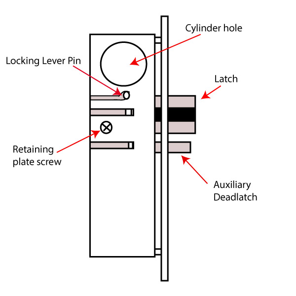
Adams Rite 4510 Latch
Although Adams Rite tech support might not want to talk about it*, depending on who you talk to there, the 4510 series latch lock, like its predecessor the 4710, is, in fact, field reversible. Following are the steps to do so.
First, try to choose a clean work surface in an enclosed space, just in case the springs go flying.
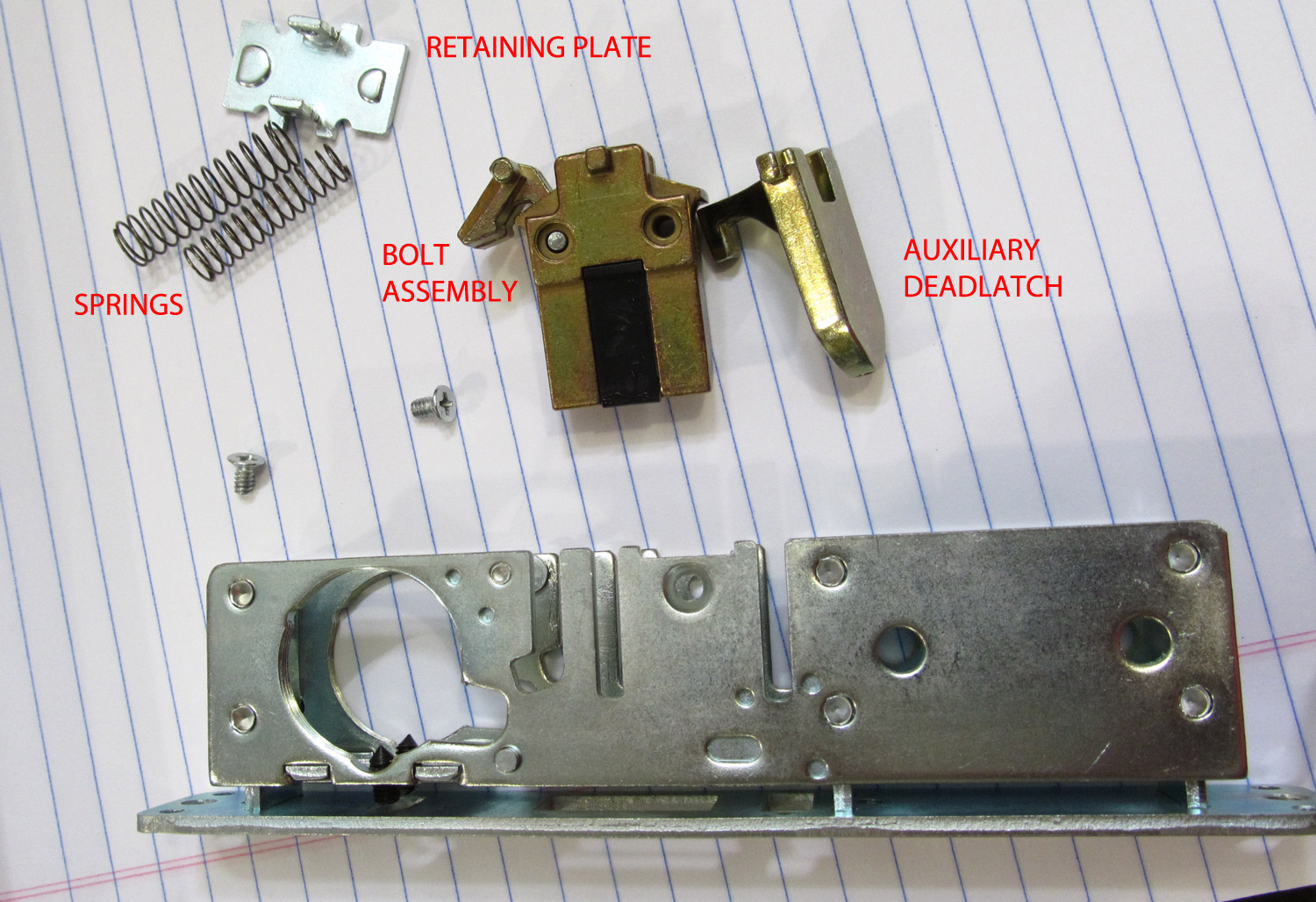
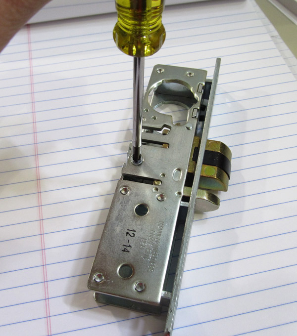
1. Remove the retaining plate screws using a #1 Philips screwdriver. Place the screws on the work surface where you can find them later.
2. Carefully remove the plate from the back of the lock body that holds the bolt, auxiliary dead latch and latch springs in place. The latch springs exert tension against this plate, so remove it with care.
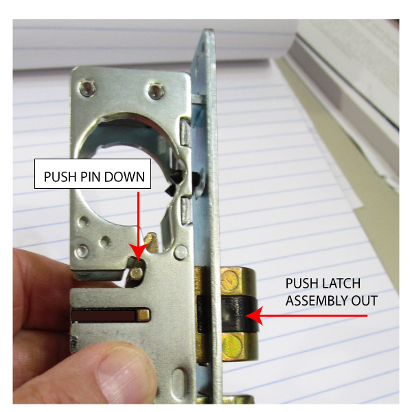
3. Using the tip of the screwdriver, move the locking lever pin so it lines up with the slot in the lock body and gently push the front of the bolt with your thumb. The bolt, auxiliary dead latch and deadlock arm assembly will slide out of the back of the lock body together.
4. Remove the pin that attaches the deadlock arm to the bolt assembly.
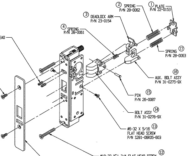
See the exploded view of the old 4710 latch below for more detail. The newer 4510 is similar if not identical to the 4710.
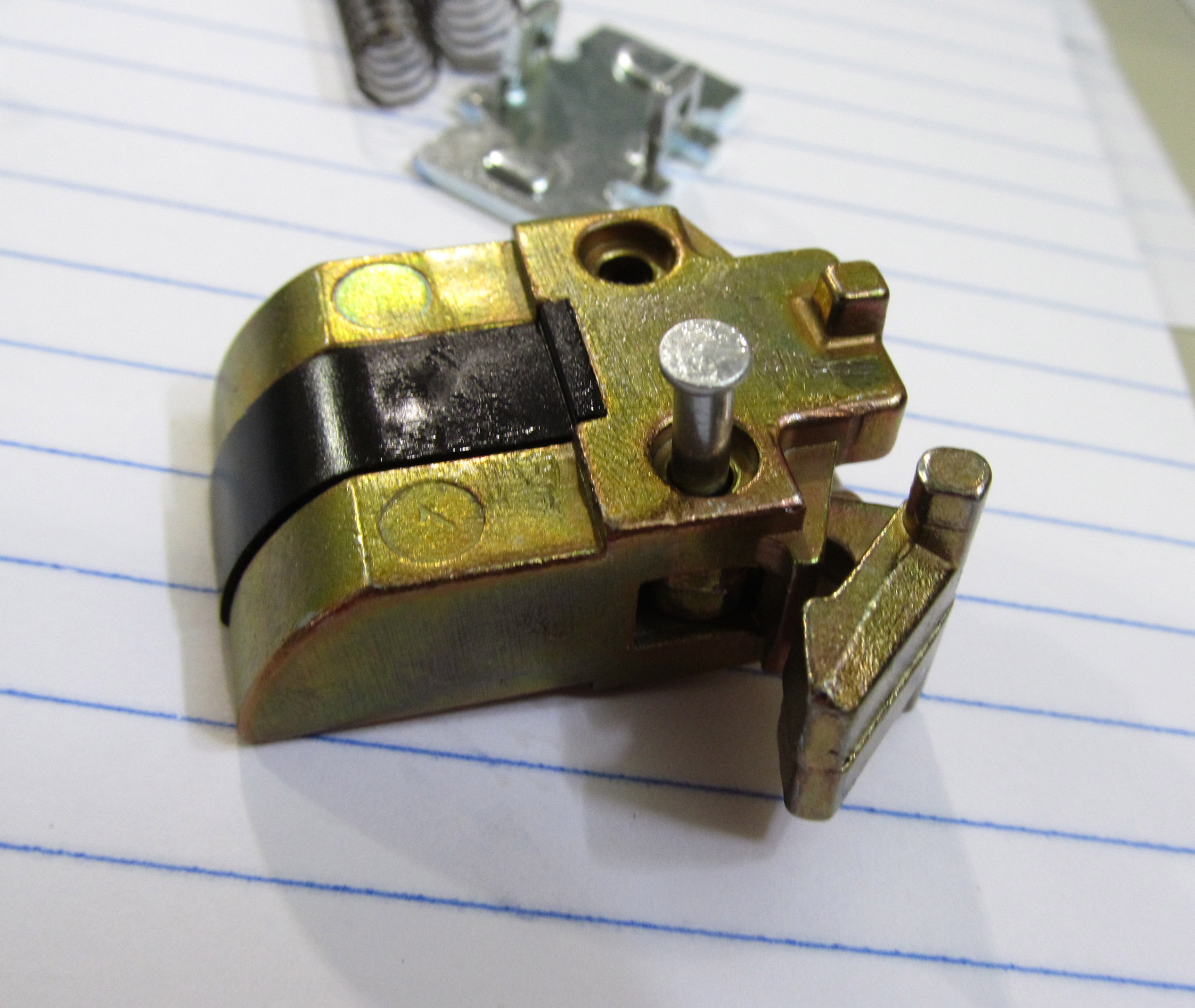
Caution: There is a spring inside the bolt assembly that actuates the deadlock arm.
5. Remove the deadlock arm and spring.
6. Turn the latch over and install the deadlock arm and spring on the other side. You will need to hold the deadlock arm and spring in position. When the spring and all are in position, install the pin.
7. Slide the bolt assembly into the lock body.
9. Place the smaller spring into the auxiliary deadlatch and the larger spring in the bolt.
8. Slide the auxiliary deadlatch into the lock body.
9. Install the retaining plate and screws.
Detail from discontinued Adams Rite 4710 Latch parts breakdown, from Adams Rite parts book
* I recently related this procedure to a locksmith who said she had called Adams Rite tech support who told her the unit is not field reversible. This is understandable because the installation instructions do not discuss reversing the handing.
Comments Off on Quest for the 24-Inch Exit Device with Electric Latch Retraction
I had a lot of fun recently trying to meet a customer’s requirement for a 4-foot by 7-foot pair of doors in a hospital that needed to be fire rated and automated. I found that Corbin and Yale (sister companies whose exit devices are almost identical) offer fire rated surface vertical rod exit devices with electric latch retraction that meet this need. The installer will be able to put some kind of little power operator on each 24-inch leaf of this four foot pair and cram two fire rated surface vertical rod devices onto these same narrow leaves. Doubtless it will look odd, but it will work.
Admittedly the whole idea is a bit dubious. True, by having both leaves opened simultaneously by power operators will provide amply more than the minimum 32-inch clearance demanded by the American Disabilities act, but if anyone manually opens either leaf it certainly will not.
Sargent and Von Duprin offer 24-inch fire rated exit devices, but neither offer them with electric latch retraction. It is unfortunately necessary to call these companies’ tech support lines in order to verify this information, since their price lists both show 24-inch possibilities without disclaiming the electric latch retraction option. Neither the Sargent nor the Von Duprin has a note to say the 24-inch device is not available with electric latch retraction that I could see; if that is in fact the case, the buyer is left to beware the exit device order that bounces back because it was ordered with options that are mutually incompatible.
It’s good advice anyway to always call the manufacturer’s tech support whenever there is a question. Waiting on hold is a lot better than storing thousand-dollar exit devices that didn’t work out on the job.
Note:A reader named Rick writes in with this about Sargent electric latch retraction: “Tom, I just stumbled across your site this evening, while doing a search for Fail Secure mag locks of all things (IR says there is one). But I saw your latest article on latch retraction units and had to clarify the Sargent restrictions. These can be found within the catalog pages, specifically the page showing the 56 option (toward the back). It says:
MinimumDoorWidths:
-Wide Stile Door 28″
– Narrow Stile Door 26″
Thank you, Rick, for this bit of info. I should add that it is always good to check all the literature at your disposal for any information you are looking for. Some manufacturers have more detail in their price list than in their catalog, and others vice versa. Thanks again.
Comments Off on New PS914RFK Retro-fit Kit from Von Duprin
According to IR tech support, the PS914RFK is a bracket and main board assembly designed to install into existing PS873 enclosures. The idea is to ease PS873 replacement and it looks to me like it will accomplish that.
In addition to the PS873, you will need to replace all existing option boards that are present.
To replace 871-2, use 900-2RS
To replace 873-BB, use 900-BBK if you need batteries included. If not, use 900-BB for the board only
To replace 873-FA, use 900-FA
To replace 873-4TD, 873-AO, or 873-SI, use 900-4RL
To replace 873-2Q, use 900-2Q
The following boards have been discontinued:
873-AL
873-AC
873-DE
In several pieces of Ingersoll Rand literature I have seen the 900-BB board depicted as if it includes batteries. It does not. So if you want your battery kit to come with batteries, you need to get the 900-BBK.
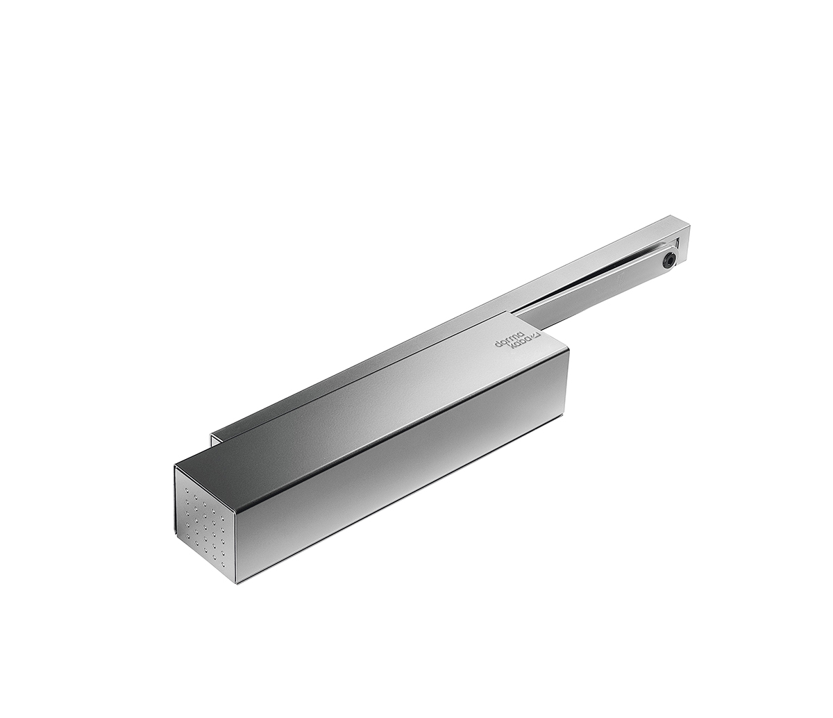
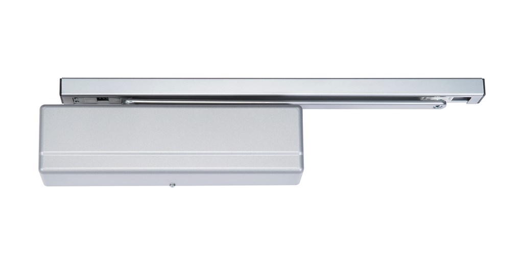
High Efficiency: According to Sargent, their model 422 cam action closer “has the highest efficiency of any surface mounted door closer on the market today. This means that a door equipped with this closer will feel light to open and have plenty of power to overcome stack pressure or other problems at latch.”
ADA Compliance: Norton states the ADA compliance advantage of cam action door closers most clearly: “cam action provides much lower opening resistance while delivering optimum closing force and control. The door closer’s wide range of adjustable closing power permits use in the most demanding situations. The efficiency and flat power curve comply with the opening force requirements of the Americans with Disabilities Act (ADA).”
Since ADA opening force requirements are a constant, compliance is measurable. Stack pressure affects are variable and more difficult to measure. I wish I had better advice than ‘try it and see,’ but I am hopeful that cam action closers may prove an effective remedy for resistant stack pressure closing issues.
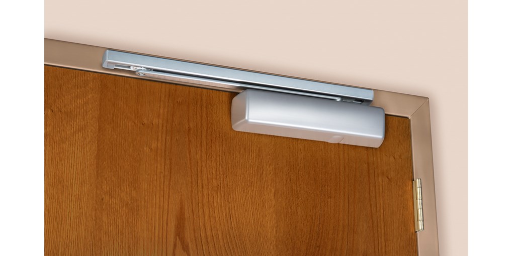
Appearance: Many architects and designers prefer track closers over closers with double lever arms because there is no arm to protrude into the space on in-swing or top jamb mounted out-swing applications, or, in parallel arm applications, necessitate a drop plate to make space.
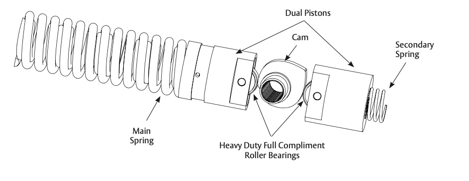
Cam Action Design
Above, the drawing from the Sargent 422 catalog shows the internal design of their cam action closer. “Closing forces are applied to the spindle through the continuous smooth surface of the cam and hardened roller bearing follower. The dual pistons’ simplified design provides a superior internal seal and reduced friction within the closer.”
Comments Off on Von Duprin Concealed Cable Exit Devices
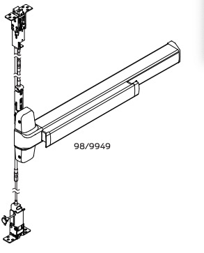
drawing from Von Duprin 98/9947, 98/9949,& 98/9950 Series Exit Devices Service manual
Von Duprin concealed cable devices have been around a while and are becoming more popular. In addition to 98/99 series devices, they also offer 33/35 series concealed cable devices. According to Allegion, these are the main advantages of concealed cable:
Designed to maintain positive latching even if alignment is not perfect due to changing door conditions
Significantly less maintenance than traditional vertical rod
Replacement parts are available- entire assembly can be removed and reinstalled while door is hanging in a matter of minutes
This from the Von Duprin Concealed Cable Datasheet:
“If a simple repair or modification is required, the cable system and latches can be removed and reinstalled by one person without removing the door from the frame.”
That’s a big deal.
Both top and bottom cables vary by height range:
Top Cable Assembly Door Opening Heights 6’0″ to 6’10”
Top Cable Assembly Door Opening Heights 6’10” to 8’0″
Top Cable Assembly Door Opening Heights >8’0″ to 9’2″
Top Cable Assembly Door Opening Heights >9’2″ to 10’4″
Bottom Cable Assembly Door Opening Heights 6’0″ to 6’10”
Bottom Cable Assembly Door Opening Heights 6’10” to 8’0″
Bottom Cable Assembly Door Opening Heights >8’0″ to 9’2″
Bottom Cable Assembly Door Opening Heights >9’2″ to 10’4″
Depending upon the height of the door, cable systems allow for ten to up to fourteen inches of adjustability. So if you are a little off on your height measurement, all is not necessarily lost. The height must fall within the range of adjustability. For example, if you order a device for an 96-inch tall door, you may have a problem if it is actually 99 inches tall.
Traditional concealed vertical rod devices (for example, 33/3547 and 98/9947) can be converted from concealed vertical rod to concealed vertical cable using the Complete Cable System package. Complete cable systems include top and bottom strikes and latches, center slides, cables and mounting packs. The part numbers for the packages are configured this way, according to the Von Duprin 2021 price book:
[exit device part number] CS [door height]
Example part number: 9949-CS-84
The install instructions for a 9949 series device show that no special tools are required for installation other than the included sizing spacer, and the cable removal tool (also included) in case you goof. Cable installation is a 15-step process.
These are not devices to install by intuition. FOLLOW THE DIRECTIONS. And good luck.
Comments Off on Electric Strike Monitors: LBM and LBSM
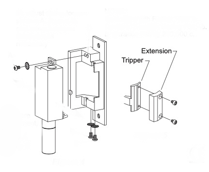
Exploded view of Von Duprin 6211 with Dual Switch option. From Von Duprin 6211 installation instructions.
LBM stands for Latch Bolt Monitor. LBSM stands for Latch Bolt and Strike Monitor, also known as LBCM and DS, depending on the manufacturer. There are probably other variations as well.
In the illustration above is shown the Von Duprin 6211. The labeled parts, “Tripper” and “Extension,” are used when the strike is equipped with the DS (dual switch) option. The DS option is Von Duprins version of LBSM. The Tripper is a piece of metal that changes the state of a switch when it is depressed by the spring-loaded force of a latch bolt when it drops into the keeper. Most other strikes use similar mechanisms to detect the presence of the latch bolt.
LBM will tell you if there is not a latch bolt present in the keeper. LBSM will tell you if there is no latch bolt present in the keeper and/or the strike itself is not in the fully locked position. Neither of these would tell you if the door is ajar. So LBM and LBSM are not true substitutes for a door position switch.
And, if someone stuffs the keeper with something to effectively keep the door unlocked or fool it into thinking there was a latch bolt there, it won’t tell you anything. On the other hand, if you don’t have LBM, someone can tape the latch back with duct tape you would have no way of knowing. The door position switch will tell you the door is closed, but you need the LBM to tell you it’s latched. The LBSM can provide you with the additional information that the electric strike is not properly locked; perhaps the keeper is not closed all the way or the internal parts are not all the way in the locked position.
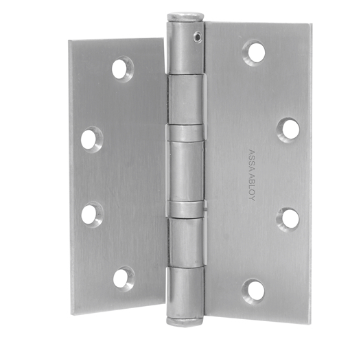
Above is pictured an interim hinge, used when your door and your frame have different sized hinge preps. For example, your frame is prepped for a five-inch by four-and-a-half inch hinge and your door is prepped for a four-and-a-half by four-and-a-half inch hinge. Why would you need such a thing? Inability to read a tape measure, perhaps?
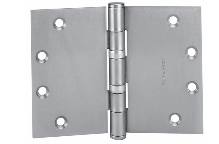
Wide Throw Hinge
Wide Throw Hinge by McKinney
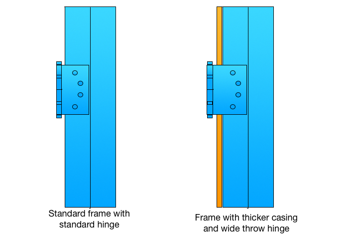
The hinge above is a wide throw hinge, used when you have a thick molding applied to the pull side face of the door frame. My illustration below shows the difference.
Sometimes people order wide throw hinges by accident because they do not know how to properly measure a full mortise hinge. Full mortise hinges are measured height first, then width. Wide throw hinges have a width that is greater than the height whereas standard hinges do not So if, for example, you order a 5 x 4-1/2 inch hinge you are getting a standard hinge and if you order a 4-1/2 x 5 inch hinge you are getting a wide throw hinge.
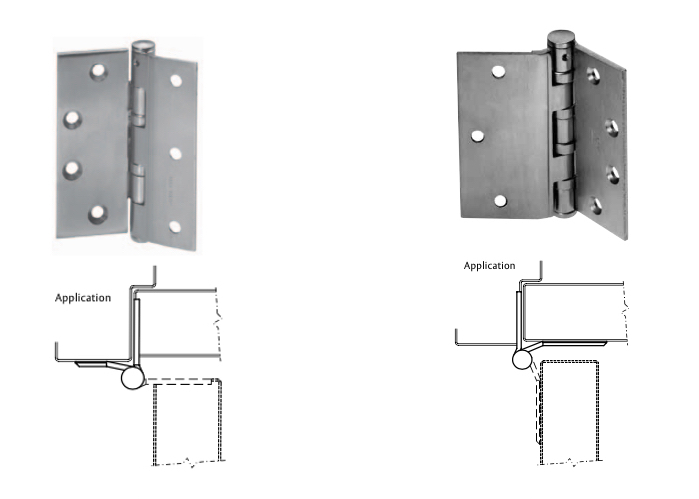
Half Mortise and Half Surface Hinges
Half Mortise and Half Surface HInges by McKinney
In the picture above, the half mortise hinge is on the left and the half surface hinge is on the right. As you can see by the “application’ drawings below each hinge, the half mortise hinge has the mortise prep on the door, and the half surface has the mortise prep on the frame. You can tell the half mortise at a glance because the surface leaf is narrow, for installation on the surface of the frame.
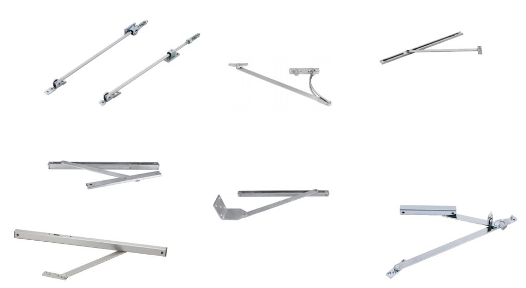
Comments Off on The Diverse World of Overhead Stops and Holders
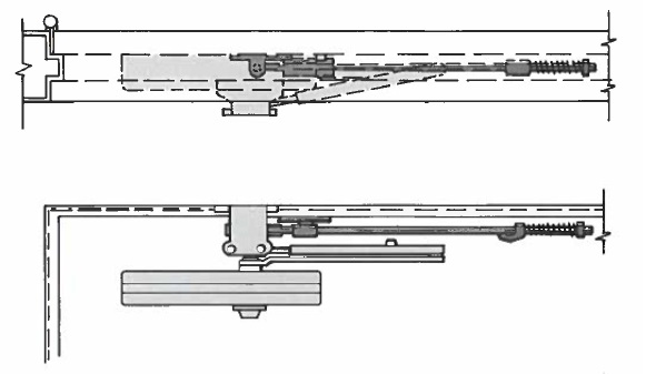
Clockwise beginning at top left: surface mounted GJ 70 and 79 series and Rixson 7 series; Rixson 6 series concealed; bottom right, GJ 81 series surface mount; bottom center, ABH 3400 series with side jamb bracket; bottom left, GJ 90 series surface mount; and above that, ABH 1000A series.
For some applications there is no truly adequate substitute for an overhead stop. Yet many times they are omitted from from hardware schedules where they should be used. But unless concealed OH stops are included at the design stage, retrofitting surface stops to a job after the fact can present a significant challenge.
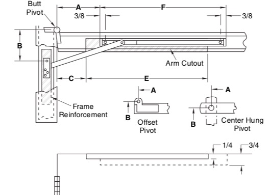
All overhead stops and holders are designed to accomplish basically the same goals, but in differing situations. If it is a stop, its purpose is to stop the door before it hits something, usually a wall. If it is a stop and holder, its purpose is to stop the door and, under the right circumstances, hold the door open. Overhead stops protect the door closer arm, and they can also make it more possible for the door closer to shut the door in high winds when the stop is templated to allow the door to open to 90 degrees or less. Maximum degree of opening with an overhead stop tends to be in 110 degree range.
Installation of surface-mounted models is simple except when a door closer is involved. Then an amount of thinking and/or additional parts may be required. This is one of the main reasons overhead stops are not often used. However, in at least one circumstance there is no comparable substitute; that is, exterior, high-use, out-swinging doors that are frequently exposed to high winds.
Most overhead stops are sized according to door width and type of hinge used, for example, you would use a 792S (size 2) for a butt hung door with an opening width of 23-1/16 inches through 27 inches, and a 793S for a door with butt hinges that is 27-1/16 inches wide through 33 inches wide. This is information found in the installation instructions. There are also adjustable overhead stops available from most manufacturers; one example is the ABH 1000A series.
The sections below discuss a few of overhead stops shown in the illustration at the top of this article.
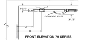
Glynn Johnson 70 and 79 Series
Glynn Johnson 70 and 79 Series Surface Mount Overhead Stops The 70 series is heavy duty and the 79 is extra-heavy duty. These are overhead stops for doors that are regularly exposed to high winds and/or abuse.
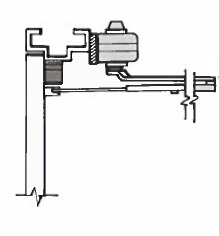
At left is a drawing of the 79 Series installed. You can see the problem of where to put the door closer.
One solution might be the LCN 1460 with 62A shoe that significantly lowers the door closer on the door as shown below:
LCN 1460 with 62A shoe and 70 series LCN overhead stop
The drawing above comes from a GJ / LCN applications guide I stumbled upon many years ago. If you look at overhead stop installation instructions, you’ll see they don’t mention a door closer. I have searched for other guides that show door closers with overhead stops, but I have found none.
If you have an aluminum-and-glass narrow stile storefront door with a 3-1/2-inch top rail, you can see that dropping the door closer this much might be a problem. At best, there would need to be a drop plate added that would show through the glass. Not pretty. Another common solution with all surface mount overhead stops is to install the stop on the push side of the door and the closer on the pull side – a viable choice on interior doors, but not usually on exterior doors.
Glynn Johnson 90 Series
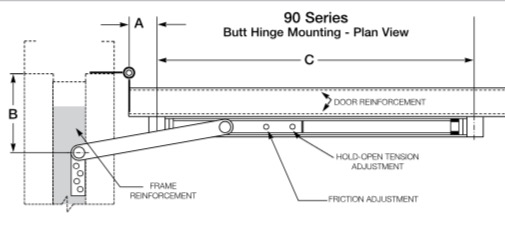
Glynn Johnson 90 Series Surface Mounted Overhead Stops This is the most common type of surface mounted overhead stop, and all overhead stop manufacturer’s make something like it.
In the drawing above you can see the space it takes up on the door. Here’s how it translates into an application with a door closer:
GJ 90 Series with LCN 1460 closer mounted top jambSide View, GJ 90 with LCN 1460 series
As you can see, this is not too bad as hardware conflicts go. The measurements are tight, but do-able.
Rixson 7 Series
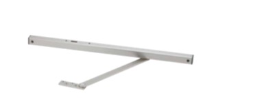
Rixson Series 7 Surface Mount Overhead Stops Rixson doesn’t talk much about this overhead stop in their catalog. They say it is ‘industrial duty,’ so, I guess, it must be well suited for high use and abuse environments like factories and warehouses. Much like the heavy spring on the GJ 70 series above, the cantilever design works as a shock-absorber. I included it because if its unique design, which is to say it looks kind of cool.
Rixson 7 Series
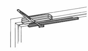
Rixson 6 Series Concealed Overhead Stops All overhead stop manufacturers make concealed overhead stops.
Concealed overhead stops have the distinct advantage that they interfere much less with the door closer installation, however they often make a difficult retrofit, especially on wood doors, sometimes requiring that the door be taken down so the mortise for the track can be cut in.
On a fire rated door this would most likely void the rating.
Rixson 6 Series
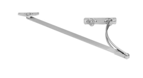
Like most Rixson overhead stops, the 6 Series is also available as the 6ADJ Series adjustable version.
Shock absorption is achieved by a heavy spring inside the track. The spring engages at the last seven inches of swing, affording a significant layer of protection for the door closer.
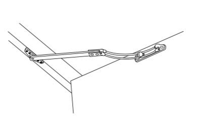
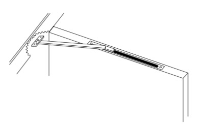
From the Rixson 6 Series install instructions.
The picture taken from the Rixson 6 Series installation instructions shows how much real estate is left on the door for a door closer, and illustrates how much better it is to be working with a concealed overhead stop rather than a surface mounted one.
Comments Off on Choosing a Power Supply for Electric Locking Devices
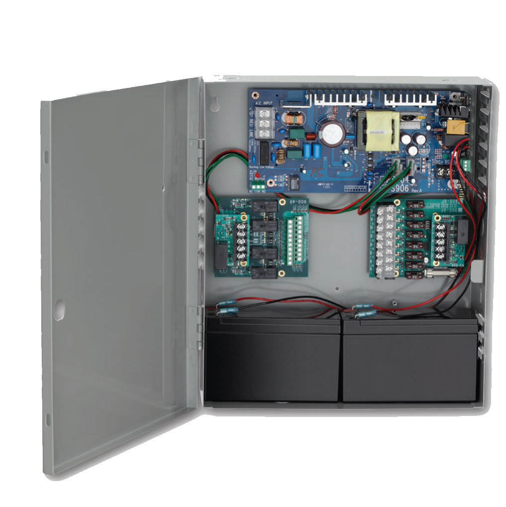
Allegion PS904 Power Supply with optional boards.
There are many ways to lock a door electrically. Here are a few of the most popular:
Electric Strike
Electromagnetic Lock
Electrified lock
Electric Latch Retraction exit device
Voltage and Current
Two main factors are universal in choosing a power supply, but some kinds of electric locking devices require special considerations. The first universal consideration is the voltage required by your electric devices. The second is the amount of current drawn by these devices.
As of this writing, most strikes, magnets and locks are field selectable for a variety of voltages, mostly 12 or 24 VDC. Some are not field selectable. Almost all electric latch retraction exit devices are 24 VDC. The important factor is, what voltage will be used to power the devices. Voltage is important (aside from the fact that running an electric device on the wrong voltage may cause a fire) because voltage affects current draw. Current draw (measured in Amperes, or ‘Amps’) determines the need for power supply capacity.
Following are examples of how the voltage affects current draw:
HES 1500 series electric strike:
.24 Amps @ 12 VDC
.12 Amps @ 24 VDC
Schlage Electronics M490 electromagnetic lock:
.65A @ 12 VDC
.35A @ 24 VDC
SDC 7800 series electrified mortise lock:
600 mA @ 12VDC
300 mA @ 24VDC
Yes, there is a trend here. 12VDC draws twice as much current as 24VDC. Good to know. A little clarification may be in order:
.24 Amps = 240 mA
Now that we have that cleared up, let’s say that we have a six-door access control project and we’re using 24VDC. On four of the doors we’ll use the HES 1500; on one door we’ll use the M490 mag and on the last door we’ll use the SDC 7800 electrified mortise lock.
Just for variety, let’s add a Sargent 80 series exit device with motorized latch retraction:
1 amp @ 24VDC
The arithmetic looks like this:
.12 + .12 + .12 + .12 + .35 + .30 + 1 = 2.13 Amps total current draw
You want to allow at least a 25% cushion so that the power supply does not have to work too hard. Therefore, rounding up, a 3-Amp power supply would be a safe bet.
Distance of Wire Run
The distance between the power supply and the appliance to be powered is also an important factor. It may determine how many power supplies you need.
Using an online voltage drop calculator I was able to determine that a 1,000-foot wire run (one-way) using 18-gauge two-conductor wire, with a current draw of 120 mA, the voltage drop will be less than 1 percent. With a 1-Amp current draw, and all other parameters the same, the voltage drop would be about 27 percent. Therefore, whereas the 1,000-foot wire run would not be a factor to run one HES 1500 strike a 120 mA, it would be a factor in powering the Sargent exit device with electric latch retraction at 1 Amp at that distance. This might mean that a separate power supply would be installed much closer to the Sargent and another power supply could power all the other devices.
Voltage drop can be managed to a degree by increasing the gauge of the wire. Using the Sargent electric latch retraction example, this time using 12-gauge wire instead of 18-gauge wire, voltage drop on a 1,000-foot one-way wire run would be 14 percent instead of 27 percent. Using thicker wire combined with moving the power supply closer to the device can mean the difference between a system that works well for years and one that soon fails.
Electric Latch Retraction Exit Devices
In many cases the industry has shifted away from solenoid-driven electric latch retraction exit devices and moving more and more toward motor-driven latch retraction. Nevertheless, those solenoid-driven devices are still out there and many are still being sold. From a power supply point of view, it is very important to understand the difference.
When solenoids are activated, the draw an “inrush” of high current for a fraction of a second. For example, a Von Duprin EL99 rim exit device draws 15 Amps at 24 VDC for one third of a second, requiring it to have a special power supply. Their power supply for this application is the PS914-2RS, which will power up to two EL devices. What makes the power supply special is (1) the circuit board equipped with capacitors that gather the current and release it when it’s big enough to do the job and (2) a delay timer that allows the power supply to power up two devices one at a time, one-third of a second apart.
There are other power supplies that will work in this application: the Altronix STRIKEIT series power supplies, or the Command Access PS220 with PM300 power booster are two such. Each will power up to two solenoid driven electric latch retraction exit devices.
As shown earlier in this article, motorized latch retraction exit devices also draw more current than other kinds of electric locking devices. However, they draw much less current than solenoid driven latch retraction exit devices. Most manufacturers say to allow 1 amp per device. Check the install instructions for your particular device to be sure.
Options
Following are some accessories you can add to make your power supply easier to install and/or service, or to add functionality.
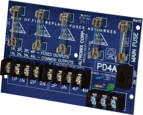
Power Distribution Board
If you have a power supply with one or two sets of outputs and need more outputs, you can add a power distribution board. The power distribution board distributes power evenly among several sets of output contacts. This can come in handy when troubleshooting a power supply that is powering multiple devices.
Altronix PD4 power distribution board.
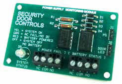
Relay Board
Relays are electrically operated switches. You flick the lights on in your room with your finger. Instead of a finger, the relay uses electricity. Relays typically draw a very small amount of electrical current. This can be useful in a variety of applications.
Security Door Controls relay board.
One example is in a simple access control system, where a receptionist pushes a button to activate an exit device with electric latch retraction that draws 1 Amp, 150 feet away. Instead of of running 1-Amp current from the power supply to the pushbutton, from the pushbutton to the device, and from the device back to the power supply, use the pushbutton to trigger a relay in the power supply to power the device. Only the few milliamps needed to power the relay will run back to the pushbutton. This makes the system much safer for the receptionist and avoids any voltage drop problems from the extra wire run back to the pushbutton.
Fire Alarm Relay
The fire alarm relay option allows connection to the fire alarm panel, so that in the event of an alarm the panel can shut off the power supply.
Logic Board
Logic boards are boards with multiple relays and internal switches. These are used to perform more complex functions, such as activating electric latch retraction exit devices and then, a fraction of a second later, activating an automatic door opener.
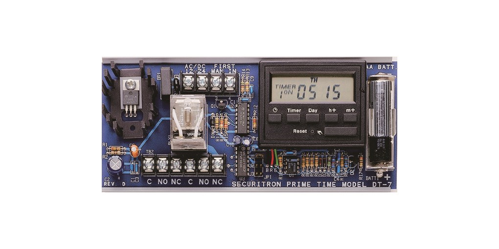
Timers
There are two main types of timers found in power supplies that are used with electric locking devices: 24-hour timers and delay timers.
24-hour timers are used to keep doors locked or unlocked for variable periods at specific times. Typically these timers can be programmed for a number of lock or unlock events. Simpler units might be used to unlock a door in the morning and then lock it back up at night every day. More versatile units can be programmed to behave differently on weekends and holidays.
Delay timers are used to time the re-locking of the electric device after it has been activated. For example, the receptionist pushes the button at her desk and immediately lets go. The timer powers the electric strike for six or seconds to allow the visitor time to push the door open.
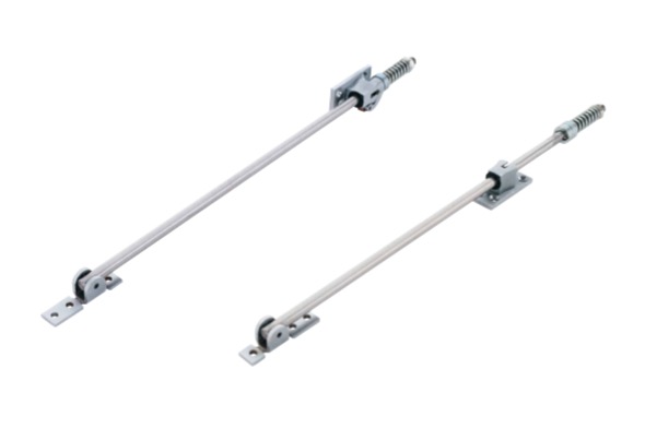
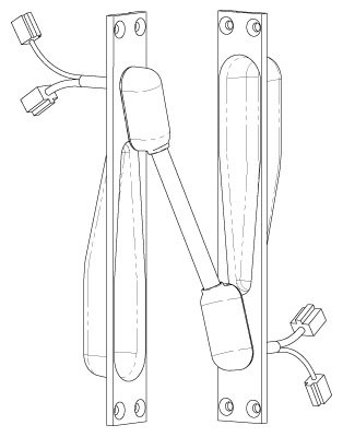
Comments Off on EPT vs. Electric Through-Wire Hinge, Revisited
Securitron CEPT
The choice between an electric through-wire hinge and an electric power transfer (EPT) is one of convenience vs. durability. Whereas the hinge requires almost no prep, the EPT does. However, the EPT is designed to minimize stress on the wires and the electrified through-wire hinge is not.
Every time the door is opened, the wire in the electric hinge is unbent and bent at least ninety degrees. With an EPT, the wire is bent at a much gentler angle. This difference translates into a big difference in durability in high traffic applications.
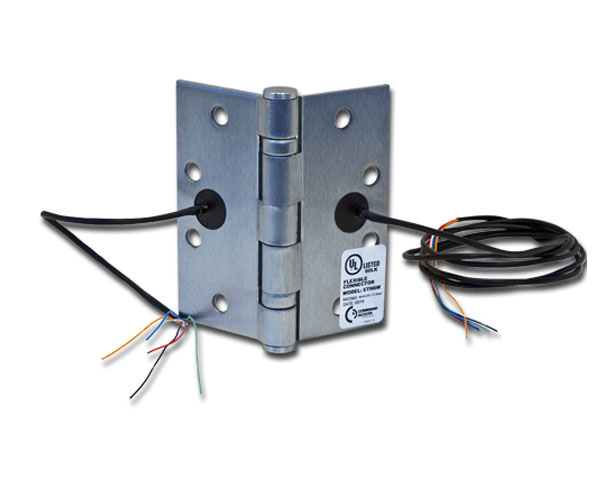
Command Access electric through-wire hinge
SDC electric through-wire hinges are UL Listed for 100,000 cycles. That means if the door were used 200 times a day for 500 days, one might expect the wires to break sometime after day 501 or so – or a life span of about a year and a half in this unusually high usage environment. Electric through-wire hinges, therefore, may not be the best choice for doors that experience very high traffic volume. The Assa Abloy EPT is rated at three million cycles, or fifteen times that of the hinge – that is, in the 200 cycles per day scenario, about twenty-two years vs. a year and a half.
This difference in durability is illustrated by the evolution of continuous hinges with through-wire electrification. Because the wires eventually break, hinge manufacturers now offer removable panels that contain the wire, so that when the wire breaks the entire 7-foot hinge need not be replaced; just the panel. While it is fairly cheap and easy to replace a 4-1/2 x 4-1/2 electric hinge, replacing a full height electrified continuous hinge is not. Replacing the removable panel is not the easiest process either, but it is much less expensive than replacing the whole hinge.
With continuous hinges as well as regular hinges, the EPT remains the far more durable choice. All continuous hinge manufacturers offer their hinges prepped for EPT; most require handing and location of prep when ordering. The projected life span of an EPT in a continuous hinge is in numbers of decades. But if you ever do have to replace one, it’s relatively easy.
 4. Remove the pin that attaches the deadlock arm to the bolt assembly.
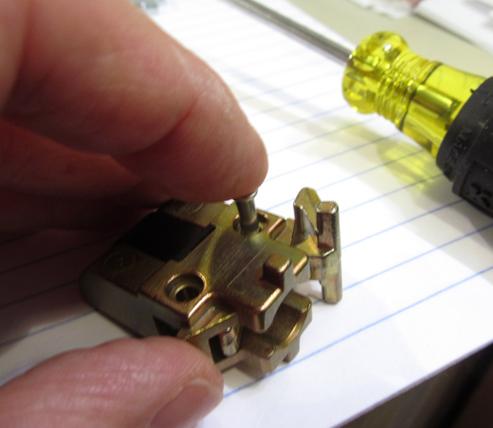
 9. Place the smaller spring into the auxiliary deadlatch and the larger spring in the bolt.